7 auto shutdown mode, 8 adc conversion start, 7 auto shutdown mode -15 – Maxim Integrated MAXQ7667 User Manual
Page 247: 8 adc conversion start sources and timing -15, Maxq7667 user’s guide, Table 14-4. adc conversion start source selection, 8 adc conversion start sources and timing
14-15
_________________________________________________________________________________________________________
MAXQ7667 User’s Guide
14.5.7 Auto Shutdown Mode
Power consumption is reduced significantly by placing the MAXQ7667 ADC in auto shutdown mode after a conversion. Auto shutdown
is ideal for infrequent data sampling and fast wake-up time applications. Auto shutdown is controlled by the SARASD bit (SARC.4). If
the SARASD bit is set, the ADC automatically shuts down when the ADC data ready (SARRDY) bit in the ASR register is set at the end
of a conversion. If the SARASD is not set, the ADC returns to acquisition mode after a conversion. Auto shutdown reduces the ADC
supply current (refer to the MAXQ7667 data sheet for exact current saving), but there is a power-up (1µs) after an auto shutdown.
Note that auto shutdown is different from a full power-down state. The ADC is disabled and fully powered down if the SARE bit in the
APE register is cleared. Full power-down reduces ADC supply current (refer to the MAXQ7667 data sheet for exact current saving) and
is ideal for infrequent data sampling. The SARE bit is the master control for ADC operation and, unless set, no ADC conversion is pos-
sible. From full power-down state (SARE = 0) the ADC requires approximately 1.0µs to power-up.
Data in the ADC SFR registers is not lost when the ADC is in auto shutdown or full power-down state.
14.5.8 ADC Conversion Start Sources and Timing
The MAXQ7667 ADC supports three different conversion start sources: timers, ADC convert pin, and software writes. The conversion
start source provides the input trigger for the ADC to start acquisition and conversion. The ADC enable bit (SARE) in the APE register
must be set so that the ADC block is enabled for operation. The ADC source select field (SARS[2:0]) in the SARC register selects the
ADC conversion start source, as shown in Table 14-4.
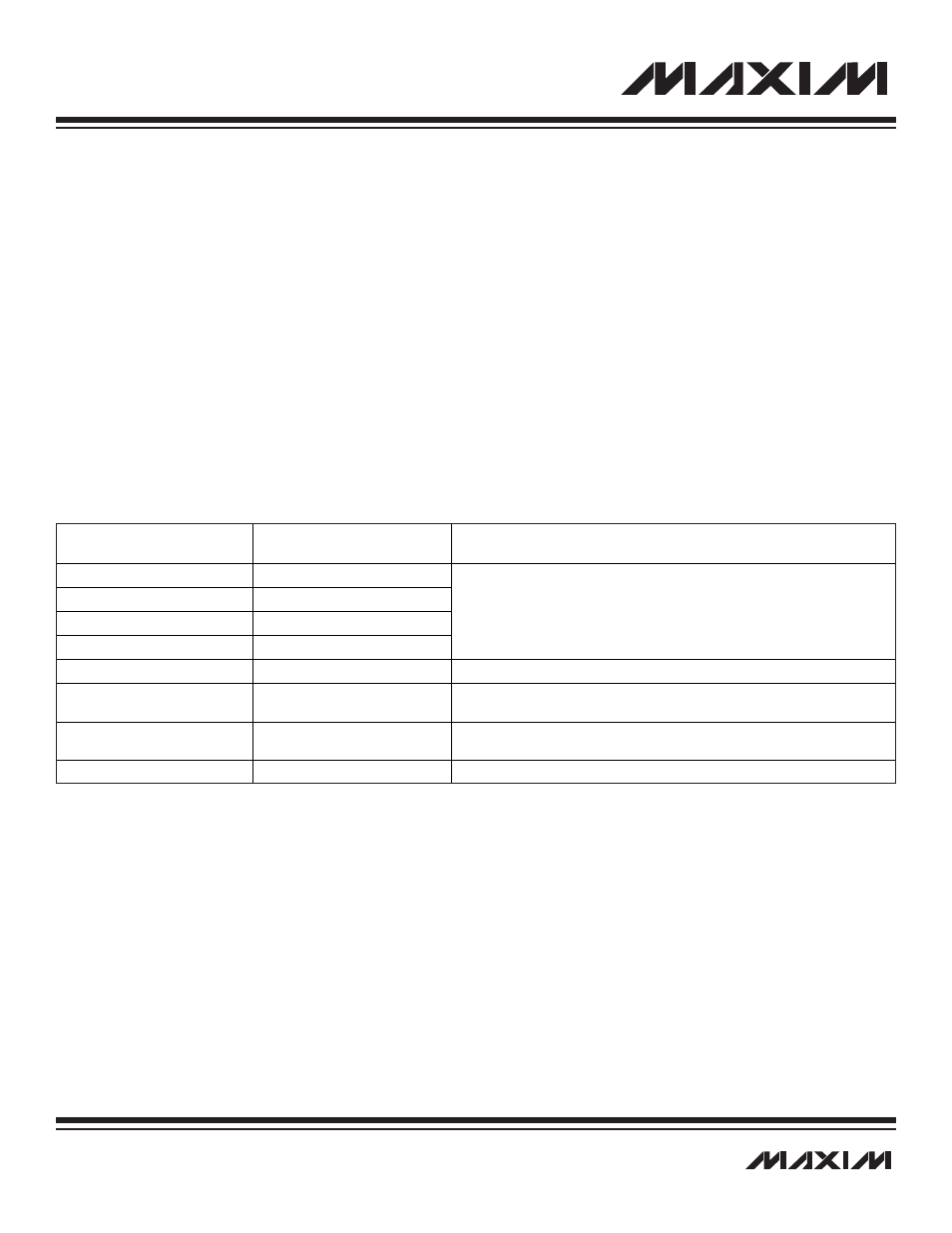
Table 14-4. ADC Conversion Start Source Selection
All three conversion start sources support single-edge or dual-edge modes of operation, which is determined by the SARDUL (SARC.6)
bit. When SARDUL is set to 1, the ADC operates in dual-edge mode. The rising edge of the selected conversion start source causes
the ADC to power-up and begin acquisition (track); the falling edge causes it to sample and perform a conversion (hold). An ADC
power-up delay is required only if ADC is in auto shutdown from a prior conversion, otherwise, there is no ADC power-up delay. When
SARDUL is 0, the ADC operates in single-edge mode. The rising edge of the selected conversion start source controls the entire con-
version, i.e., power-up, acquisition, and conversion if the ADC was off (auto shutdown); if the ADC was on, it stays in acquisition mode
until the rising edge and then starts conversion. Table 14-5 summarizes ADC operation in dual- and single-edge modes.
ADC SOURCE SELECT
(SARS2:SARS0)
ADC CONVERSION
START SOURCE
DESCRIPTION
000
Timer 0
001
Timer 1
010
Timer 2
011
Reserved
•
Timer output is internally connected to ADC to act as the ADC conversion
trigger control.
•
Configure timer for 8-bit or 16-bit operation.
100
ADC Conversion Pin
This configures ADCCTL pin as ADC conversion trigger control input pin.
101
ADC Conversion Pin with Inverted
Data
This configures ADCCTL pin as ADC conversion trigger control input pin.
ADCCTL pin input is inverted and used as ADC conversion trigger control.
110
Continuous Conversion
Writing 110 to SARS[2:0] triggers conversion. Once started ADC continuously
performs a conversion every 16 ADC clock cycles.
111
SARBY (SARC.3) Bit
Write to start/busy bit triggers conversion.