4 burst signal generation, 1 setting up the hardware, 1 external rc filter – Maxim Integrated MAXQ7667 User Manual
Page 299: 2 ultrasonic transducer, 2 setting up the regist, 1 turning on the pll, 4 burst signal generation -17, 1 setting up the hardware -17, 1 external rc filter (filt) -17, 2 ultrasonic transducer -17
17.4 Burst Signal Generation
To facilitate implementation the following items must be addressed:
•
Hardware Setup:
External RC Filter (FILT)
Ultrasonic Transducer
•
Software Setup:
Turning On the PLL and the Clock Sections
Configuring the Burst Registers
Triggering the Burst Signal
17.4.1 Setting Up the Hardware
17.4.1.1 External RC Filter (FILT)
An external filter must be connected to the FILT pin if the PLL is used. This filter consists of two capacitors and one resistor (R1 = 24k
Ω,
C1 = 0.033µF, and C2 = 330pF) as shown in Figure 17-1. These values are appropriate for the entire PLL frequency range. These com-
ponents are used to filter the analog voltage that controls the voltage-controlled oscillator, VCO, in the PLL. The FILT pin can be mon-
itored with an oscilloscope to gauge the settling time of a change in the PLL frequency setting.
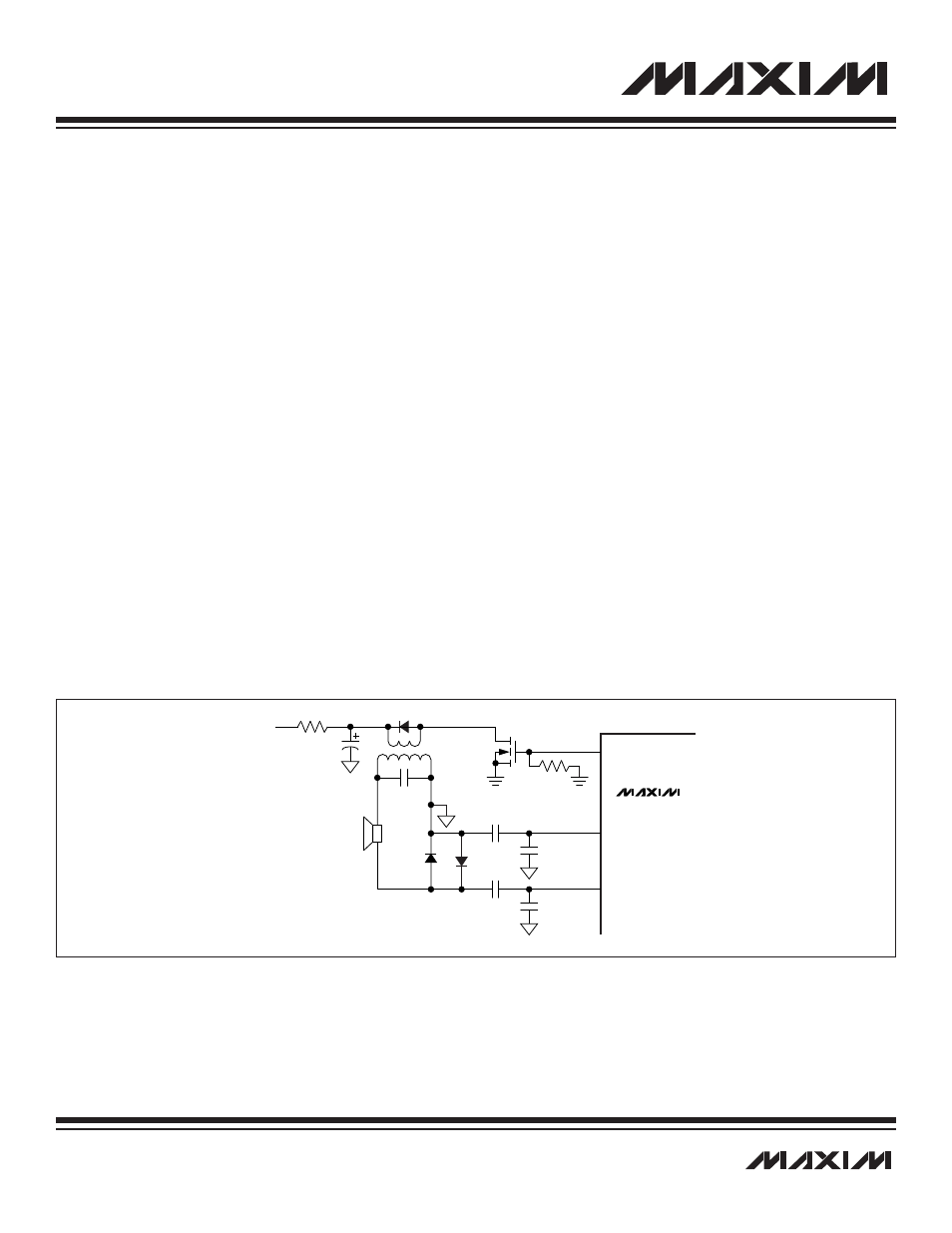
17.4.1.2 Ultrasonic Transducer
There are many ways to connect the ultrasonic transducer to the BURST pin. Figure 17-3 shows one of the possibilities.
17.4.2 Setting Up the Registers in Software
17.4.2.1 Turning On the PLL and the Clock Sections
To reduce power consumption, many sections of the MAXQ7667 are not powered up unless needed. To turn on the PLL, set the PLLE
bit (APE.3) to 1. The MAXQ7667 operates from the internal RC oscillator at power-up and only switches to the crystal-controlled clock
if instructed to by the software. To turn on the precision system clock that is controlled by the external crystal or resonator, set the XTE
bit (OSCC.1) to 1 (see Section 15).
17-17
_________________________________________________________________________________________________________
MAXQ7667 User’s Guide
MAXQ7667
0.01
µF
470pF
BURST
12V
TRANSDUCER
ECHON
0.01
µF
470pF
ECHOP
Figure 17-3. Circuit for Ultrasonic Distance Measurement