2 register space, 2 register space -8, Maxq7667 user’s guide – Maxim Integrated MAXQ7667 User Manual
Page 13
___________________________________________________________________________________________________________
2-8
MAXQ7667 User’s Guide
2.2.2 Register Space
The MAXQ7667 architecture provides a total of 16 register modules. Each of these modules contains 32 registers. Of these possible
16 register modules, only 13 are used on the MAXQ7667—seven for system registers and six for peripheral registers. The first eight
registers in each module may be read from or written to in a single cycle; the second eight registers may be read from in a single cycle
and written to in two cycles (by using the prefix register PFX); the last 16 registers may be read or written in two cycles (always requir-
ing use of the prefix register PFX).
Registers may be either 8 or 16 bits in length. Within a register, any number of bits can be implemented; bits not implemented are fixed
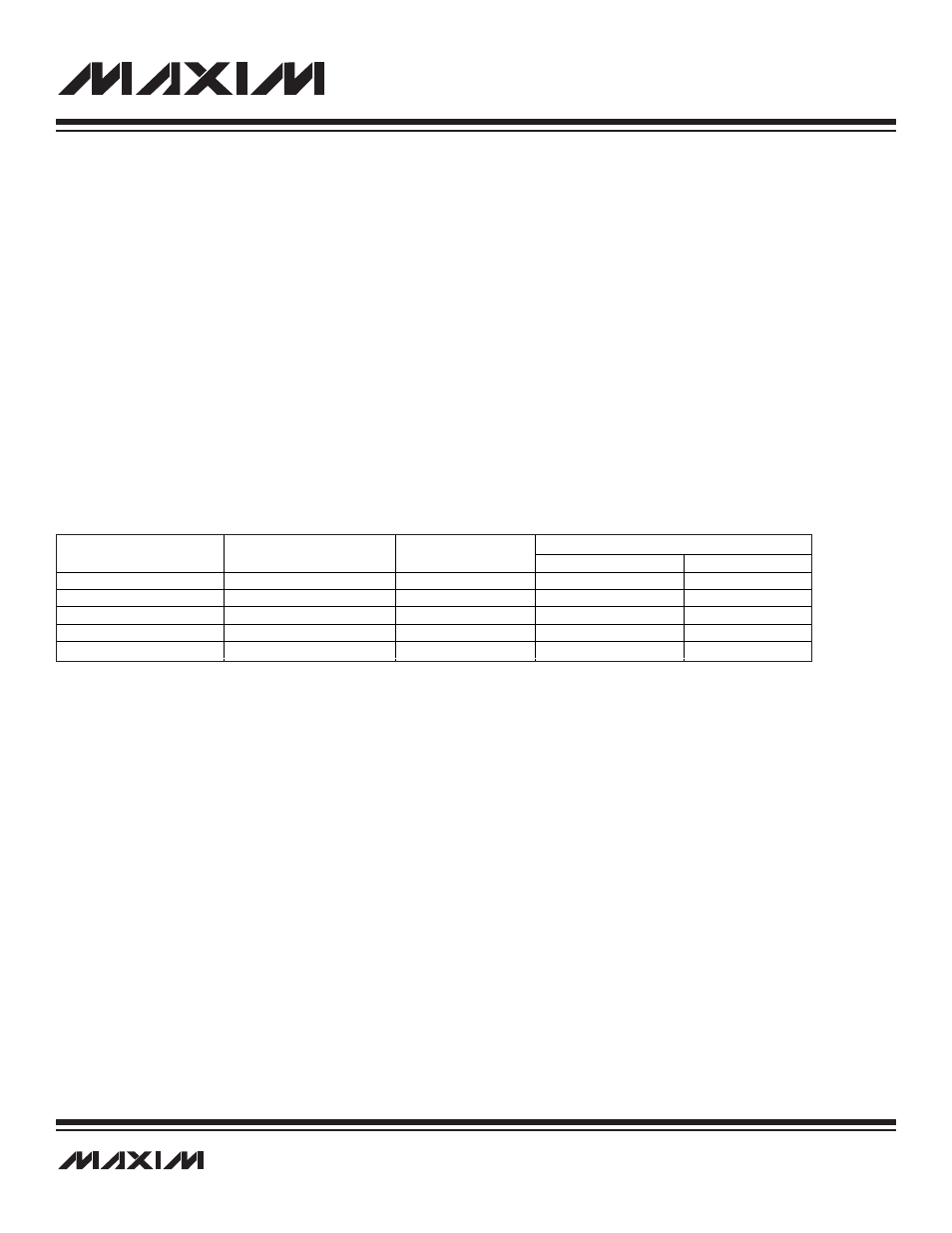
at zero. Data transfers between registers of different sizes are handled as shown in Table 2-1.
•
If the source and destination registers are both 8 bits wide, data is transferred bit to bit accordingly.
•
If the source register is 8 bits wide and the destination register is 16 bits wide, the data from the source register is transferred
into the lower 8 bits of the destination register. The upper 8 bits of the destination register are set to the current value of the pre-
fix register; this value is normally zero, but it can be set to a different value by the previous instruction if needed. The prefix reg-
ister reverts back to zero after one cycle, so this must be done by the instruction immediately before the one that will be using
the value.
•
If the source register is 16 bits wide and the destination register is 8 bits wide, the lower 8 bits of the source are transferred to
the destination register.
•
If both registers are 16 bits wide, data is copied bit to bit.
Table 2-1. Register-to-Register Transfer Operations
The above rules apply to all data movements between defined registers. Data transfer to/from undefined register locations has the fol-
lowing behavior:
•
If the destination is an undefined register, the MOVE is a dummy operation but may trigger an underlying operation according
to the source register (e.g., @DP[n]--).
•
If the destination is a defined register and the source is undefined, the source data for the transfer will depend upon the source mod-
ule width. If the source is from a module containing 8-bit or 8-bit and 16-bit source registers, the source data will be equal to the pre-
fix data concatenated with 00h. If the source is from a module containing only 16-bit source registers, 0000h source data is used for
the transfer.
The 16 available register modules are broken up into two different groups. The low six modules (specifiers 0h through 5h) are known
as the Peripheral Register modules, while the high 10 modules (specifiers 6h to Fh) are known as the System Register modules. These
groupings are descriptive only, as there is no difference between accessing the two register groups from a programming perspective.
The System Registers define basic functionality that remains the same across all products based on the MAXQ architecture. This
includes all register locations that are used to implement higher-level op codes as well as the following common system features.
•
ALU (MAXQ20: 16 bits) and associated status flags (zero, equals, carry, sign, overflow)
•
Eight working accumulator registers (MAXQ20: 16-bit width), along with associated control registers
•
Instruction pointer
•
Registers for interrupt control, handling, and identification
•
Autodecrementing loop counters for fast, compact looping
•
Two data pointer registers and a frame pointer for data memory access
DESTINATION SET TO VALUE
SOURCE REGISTER SIZE
(BITS)
DESTINATION REGISTER
SIZE (BITS)
PREFIX SET?
HIGH 8 BITS
LOW 8 BITS
8
8
—
Source [7:0]
8
16
No
00h
Source [7:0]
8
16
Yes
Prefix [7:0]
Source [7:0]
16
8
—
Source [7:0]
16
16
No
Source [15:8]
Source [7:0]