Figure 14-5. bipolar transfer function -13, Table 14-3. bipolar code table -13, Maxq7667 user’s guide – Maxim Integrated MAXQ7667 User Manual
Page 245: Table 14-3. bipolar code table
14-13
_________________________________________________________________________________________________________
MAXQ7667 User’s Guide
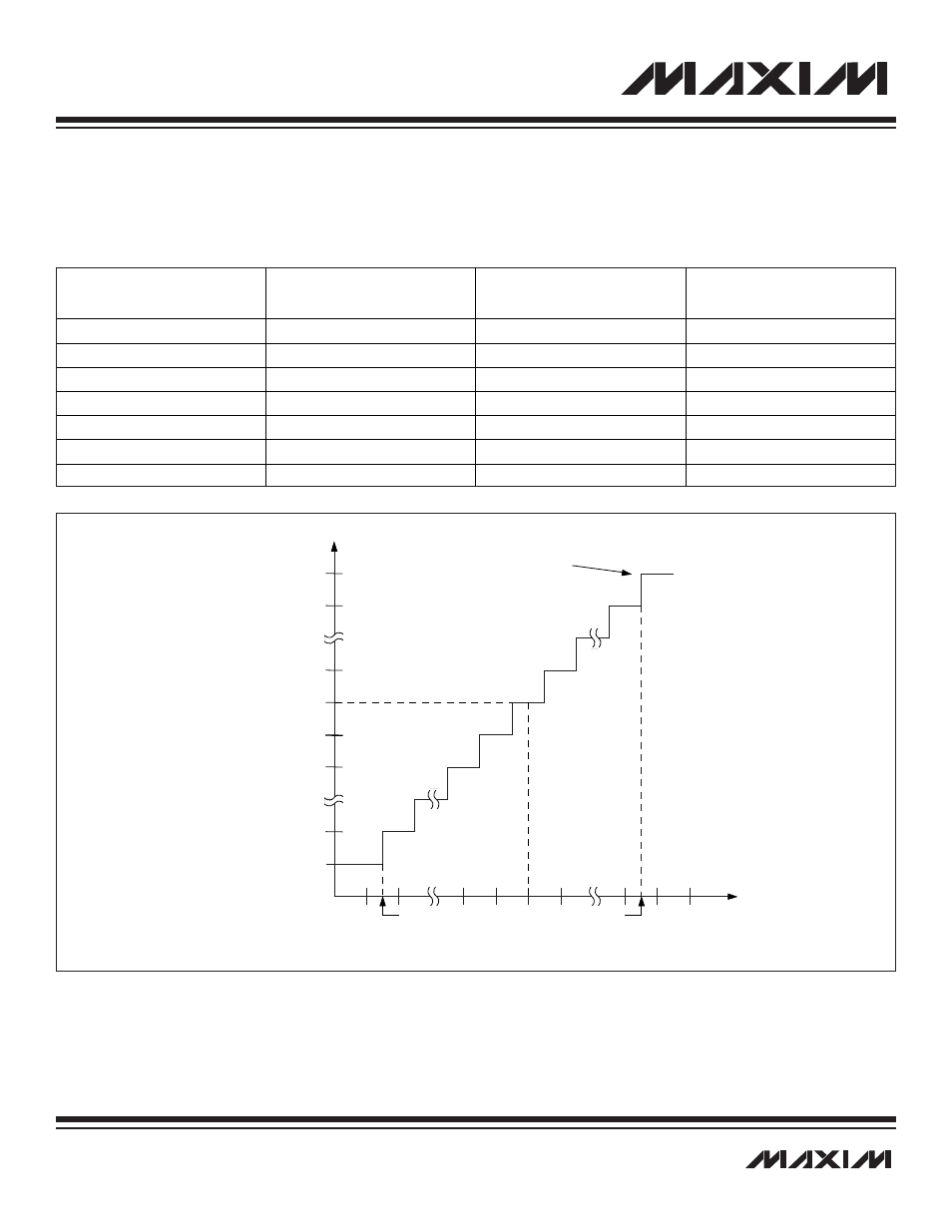
The MAXQ7667 ADC output is two’s complement in bipolar mode. Figure 14-5 shows the MAXQ7667 ADC bipolar transfer function.
Table 14-3 shows the bipolar relationship between the differential analog input voltage and the digital output code. In bipolar mode,
the inputs are measured in a truly differential fashion where either input can exceed the other by up to REF/2.
Figure 14-5. Bipolar Transfer Function
800
801
FFE
001
000
FFF
7FE
7FF
-FS
0
+FS
O
U
T
P
U
T
C
O
D
E
(h
e
x
)
DIFFERENTIAL INPUT VOLTAGE (LSB)
+FS - 1.5 LSB
FULL-SCALE
TRANSITION
+FS = REF/2
ZS = 0
-FS + 0.5 LSB
-FS = -REF/2
1 LSB = REF/4096
Table 14-3. Bipolar Code Table
BINARY DIGITAL
OUTPUT CODE
D11–D0
HEXADECIMAL
EQUIVALENT OF
D11–D0
DECIMAL
EQUIVALENT OF
D11–D0 (CODE
12
)
DIFFERENTIAL INPUT
VOLTAGE (V)
(EXTERNAL, REF = 2.5V)
0111 1111 1111
0x7FF
+2047
+1.24939 ± 0.5 LSB
0111 1111 1110
0x7FE
+2046
+1.248779 ± 0.5 LSB
0000 0000 0001
0x001
+1
+0.00061 ± 0.5 LSB
0000 0000 0000
0x000
0
0.000 ± 0.5 LSB
1111 1111 1111
0xFFF
-1
-0.00061 ± 0.5 LSB
1000 0000 0001
0x801
-2047
-1.24939 ± 0.5 LSB
1000 0000 0000
0x800
-2048
-1.25 ± 0.5 LSB