Allied Telesis AT-S70 User Manual
Page 268
Appendix B: DIP Switch Settings
268
AT-CM20x and AT-CM212x/1 Series Line Cards DIP Switches
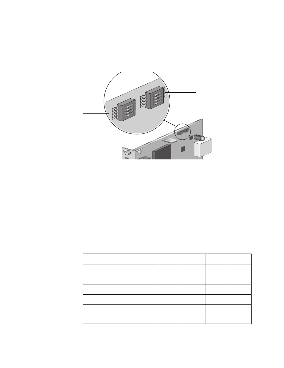
The AT-CM2xx series line cards feature two sets of DIP switches labeled
“SW1” and “SW 2” as shown in Figure 89.
Figure 89. DIP Switch Sets on an AT-CM2xx Series Line Card
The DIP switches in the SW 1 DIP switch set allow you to set the
operating mode of the line card. For information about the operating
modes, refer to “Configuring the Line Card Operating Mode” on page 67.
The DIP switches in the SW 2 DIP switch set allow you to configure the
MDI/MDI-X feature on the twisted pair port.
Table 6 shows how to enable the operating mode on an AT-CM20x Series
or AT-CM212x/1 Series line card by setting the DIP switches in the SW1
DIP switch set.
“X” means that the DIP switch position can be ON or OFF.
1 2
3 4
1 2
3 4
AT-CM20
2
LK
1 2
3 4
1 2
3 4
SW1
SW2
ON
ON
SW 2 DIP Switch Set
SW 1 DIP Switch Set
Table 6. SW 1 DIP Switch Set (Operating Mode) for the AT-CM20x Series
and AT-CM212x/1 Series Line Cards
Operating Mode
DIP 1
DIP 2
DIP 3
DIP 4
Smart MissingLink (SML)
OFF
ON
ON
X
MissingLink™ (ML)
OFF
OFF
ON
X
OAM Bypass
ON
OFF
OFF
X
OAM Visible
ON
ON
OFF
X
Link Test (default)
OFF
OFF
OFF
X
Manufacturing Default Settings
OFF
OFF
OFF
OFF