Verify the configuration, Ipv6 static route configuration example, Network requirements – H3C Technologies H3C WX6000 Series Access Controllers User Manual
Page 193: Configuration outlines, Configuration procedure, Ipv6 static route configuration example -7

25-7
Verify the configuration
# Display the route table.
Enter the IPv4 route page of Switch A, Switch B, and AC respectively to verify that the newly configured
static routes are displayed as active routes on the page.
# Use the ping command for verification.
Ping Host B from Host A (assuming both hosts run Windows XP).
C:\Documents and Settings\Administrator>ping 1.1.3.2
Pinging 1.1.3.2 with 32 bytes of data:
Reply from 1.1.3.2: bytes=32 time=1ms TTL=128
Reply from 1.1.3.2: bytes=32 time=1ms TTL=128
Reply from 1.1.3.2: bytes=32 time=1ms TTL=128
Reply from 1.1.3.2: bytes=32 time=1ms TTL=128
Ping statistics for 1.1.3.2:
Packets: Sent = 4, Received = 4, Lost = 0 (0% loss),
Approximate round trip times in milli-seconds:
Minimum = 1ms, Maximum = 1ms, Average = 1ms
IPv6 Static Route Configuration Example
Network requirements
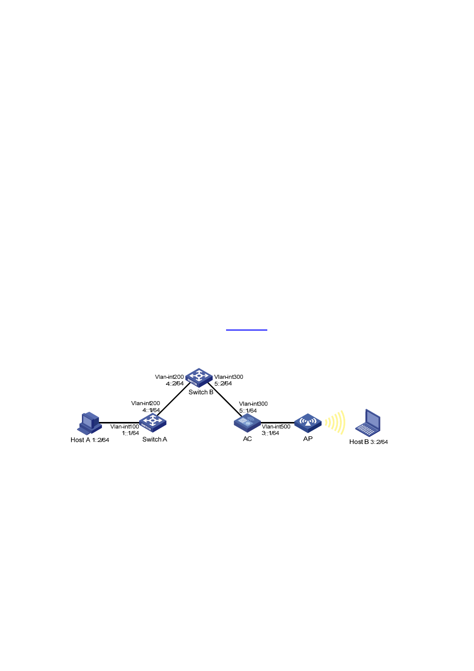
The IP addresses of devices are shown in
. IPv6 static routes need to be configured on
Switch A, Switch B and AC for Host A and Host B to communicate with each other.
Figure 25-7 Network diagram for IPv6 static route configuration
Configuration outlines
1) On Switch A, configure a default route with Switch B as the next hop.
2) On Switch B, configure one static route with Switch A as the next hop and the other with AC as the
next hop.
3) On AC, configure a default route with Switch B as the next hop.
Configuration procedure
1) Configure IPv6 addresses for interfaces (omitted)
2) Configure IPv6 static routes on the switches.
# Configure a default route with the next hop address 4::2 on Switch A (omitted).
# Configure two static routes on Switch B: one with destination address 1::/64 and next hop address
4::1, and the other with destination address 3::/64 and next hop address 5::1 (omitted).
