5 subclock input circuit, 6 waveform forming circuit – Renesas H8S/2111B User Manual
Page 494
Rev. 1.00, 05/04, page 460 of 544
19.5
Subclock Input Circuit
The subclock input circuit controls subclock input from the EXCL pin. To use the subclock, a
32.768-kHz external clock should be input from the EXCL pin. At this time, the P96DDR bit in
P9DDR should be cleared to 0, and the EXCLE bit in LPWRCR should be set to 1.
Subclock input conditions are shown in table 19.5. When the subclock is not used, subclock input
should not be enabled.
Table 19.5 Subclock Input Conditions
Vcc = 3.0 to 3.6 V
Item Symbol
Min
Typ
Max
Unit
Measurement
Condition
Subclock input pulse width
low level
t
EXCLL
— 15.26
—
µs
Subclock input pulse width
high level
t
EXCLH
— 15.26
—
µs
Subclock input rising time
t
EXCLr
— — 10 ns
Subclock input falling time
t
EXCLf
— — 10 ns
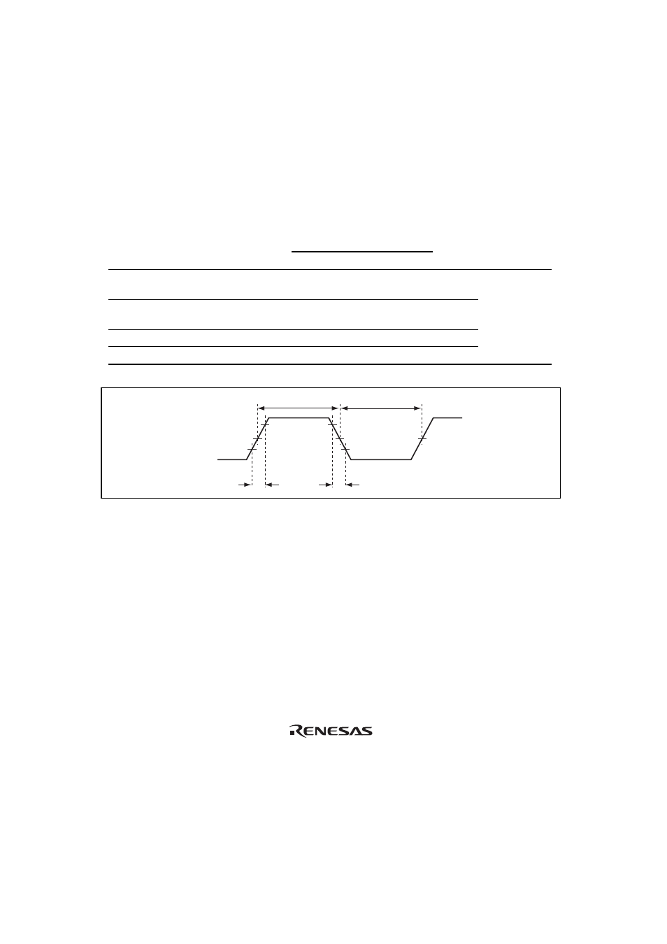
Figure 19.7
t
EXCLH
t
EXCLL
t
EXCLr
t
EXCLf
V
CC
× 0.5
EXCL
Figure 19.7 Subclock Input Timing
19.6 Waveform
Forming
Circuit
To remove noise from the subclock input at the EXCL pin, the subclock is sampled by a divided
φ
clock. The sampling frequency is set by the NESEL bit in LPWRCR.
The subclock is not sampled in subactive mode, subsleep mode, or watch mode.