4 input data registers 1 to 3 (idr1 to idr3) – Renesas H8S/2111B User Manual
Page 414
Rev. 1.00, 05/04, page 380 of 544
Table 15.2 Register Selection
I/O Address
Bit 4
Bit 3
Bit 2
Bit 1
Bit 0
Transfer
Cycle
Host Register Selection
Bit 4
Bit 3
0
Bit 1
0
I/O write
IDR3 write, C/
D3 ← 0
Bit 4
Bit 3
1
Bit 1
0
I/O write
IDR3 write, C/
D3 ← 1
Bit 4
Bit 3
0
Bit 1
0
I/O read
ODR3 read
Bit 4
Bit 3
1
Bit 1
0
I/O read
STR3 read
Bit 4
0 0 0 0 I/O
write
TWR0MW
write
0 0 0 1
Bit 4
1 1 1 1
I/O write
TWR1 to TWR15 write
Bit 4
0 0 0 0 I/O
read
TWR0SW
read
0 0 0 1 I/O
read
Bit 4
1 1 1 1
TWR1 to TWR15 read
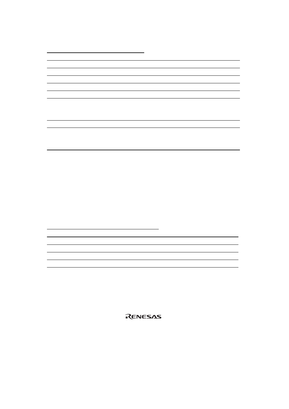
15.3.4
Input Data Registers 1 to 3 (IDR1 to IDR3)
The IDR registers are 8-bit read-only registers for the slave processor (this LSI), and 8-bit write-
only registers for the host processor. The registers selected from the host according to the I/O
address are shown in the following table. For information on IDR3 selection, see section 15.3.3,
LPC Channel 3 Address Register (LADR3). Data transferred in an LPC I/O write cycle is written
to the selected register. The state of bit 2 of the I/O address is latched into the C/
D bit in STR, to
indicate whether the written information is a command or data. The initial values of IDR1 to IDR3
are undefined.
I/O Address
Bits 15 to 4
Bit 3
Bit 2
Bit 1
Bit 0
Transfer
Cycle
Host Register Selection
0000
0000
0110
0 0 0 0 I/O
write
IDR1 write, C/
D1 ← 0
0000
0000
0110
0 1 0 0 I/O
write
IDR1 write, C/
D1 ← 1
0000
0000
0110
0 0 1 0 I/O
write
IDR2 write, C/
D2 ← 0
0000
0000
0110
0 1 1 0 I/O
write
IDR2 write, C/
D2 ← 1