Figure 12.7 sample serial transmission flowchart – Renesas H8S/2111B User Manual
Page 289
Rev. 1.00, 05/04, page 255 of 544
No
[1]
Yes
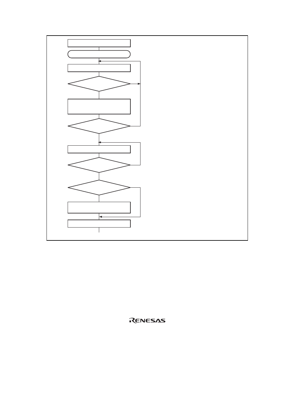
Initialization
Start transmission
Read TDRE flag in SSR
[2]
Write transmit data to TDR
and clear TDRE flag in SSR to 0
No
Yes
No
Yes
Read TEND flag in SSR
[3]
No
Yes
[4]
Clear DR to 0 and
set DDR to 1
Clear TE bit in SCR to 0
TDRE = 1
All data transmitted?
TEND = 1
Break output?
[1] SCI
initialization:
The TxD pin is automatically designated
as the transmit data output pin.
After the TE bit is set to 1, a frame of 1s
is output, and transmission is enabled.
[2] SCI status check and transmit data
write:
Read SSR and check that the TDRE flag
is set to 1, then write transmit data to
TDR and clear the TDRE flag to 0.
[3] Serial transmission continuation
procedure:
To continue serial transmission, read 1
from the TDRE flag to confirm that
writing is possible, then write data to
TDR, and clear the TDRE flag to 0.
[4] Break output at the end of serial
transmission:
To output a break in serial transmission,
set DDR for the port corresponding to
the TxD pin to 1, clear DR to 0, then
clear the TE bit in SCR to 0.
Figure 12.7 Sample Serial Transmission Flowchart