Renesas H8S/2111B User Manual
Page 109
Rev. 1.00, 05/04, page 75 of 544
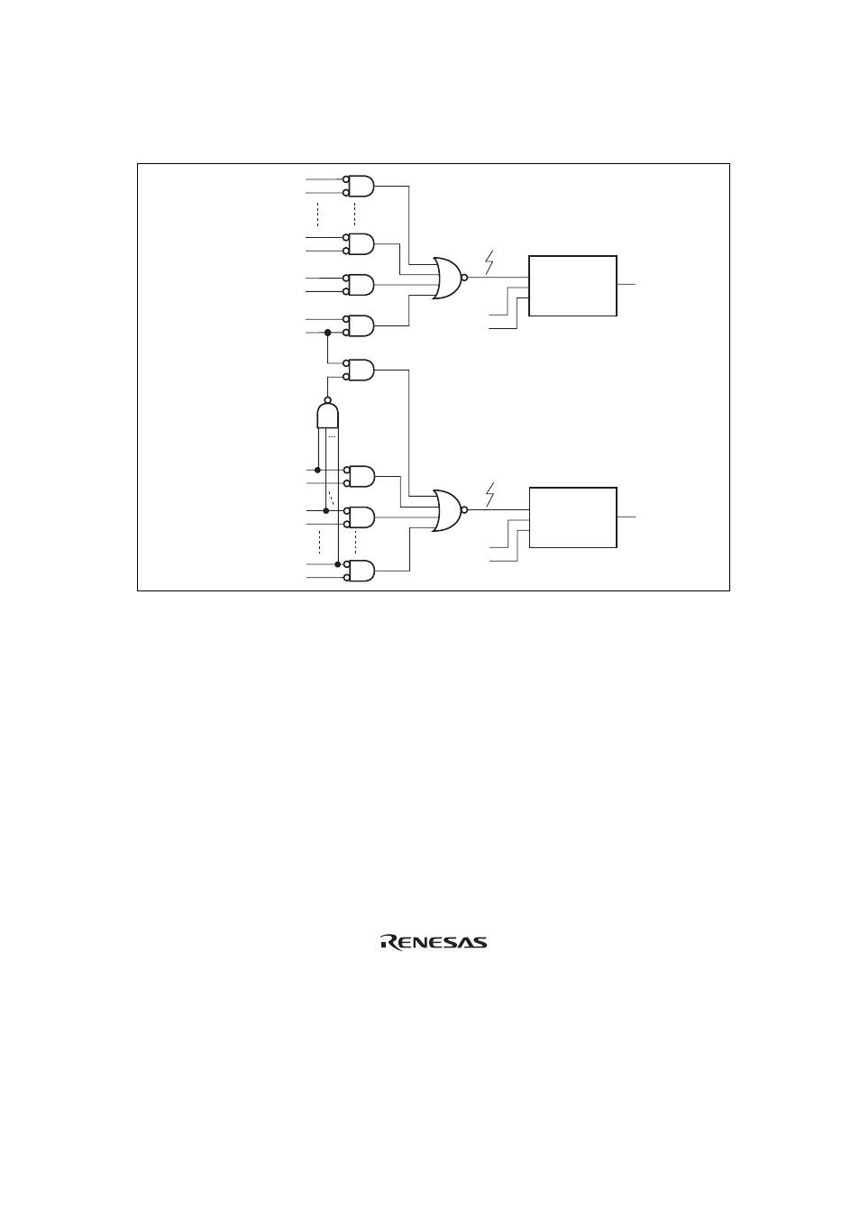
Figure 5.2 shows the relationship between interrupts IRQ7 and IRQ6, interrupts KIN15 to KIN0,
interrupts WUE7 to WUE0, and registers KMIMRA, KMIMR, and WUEMRB.
IRQ6 internal signal
IRQ6E
Edge level
selection
enable/disable
circuit
Edge level
selection
enable/disable
circuit
IRQ6SC
IRQ6
interrupt
KMIMR0 (initial value 1)
P60/
KIN0
KMIMR5 (initial value 1)
P65/
KIN5
KMIMR6 (initial value 0)
P66/
KIN6/IRQ6
KMIMR7 (initial value 1)
P67/
KIN7/IRQ7
IRQ7 internal signal
IRQ7E
IRQ7SC
IRQ7
interrupt
KMIMR8 (initial value 1)
PA0/
KIN8
KMIMR9 (initial value 1)
PA1/
KIN9
WUEMR7 (initial value 1)
PB7/
WUE7
Figure 5.2 Relationship between Interrupts IRQ7 and IRQ6, Interrupts KIN15 to KIN0,
Interrupts WUE7 to WUE0, and Registers KMIMR, KMIMRA, and WUEMRB
If any of bits KMIMR15 to KMIMR8 or WUEMRB7 to WUEMRB0 is cleared to 0, interrupt
input from the
IRQ7 pin will be ignored. When pins KIN7 to KIN0, KIN15 to KIN8, or WUE7 to
WUE0 are used as key-sense interrupt input pins or wakeup event interrupt input pins, either low-
level sensing or falling-edge sensing must be designated as the interrupt sense condition for the
corresponding interrupt source (IRQ6 or IRQ7).