1 oscillator, 1 connecting crystal resonator – Renesas H8S/2111B User Manual
Page 490
Rev. 1.00, 05/04, page 456 of 544
19.1 Oscillator
Clock pulses can be supplied either by connecting a crystal resonator, or by providing external
clock input.
19.1.1 Connecting
Crystal
Resonator
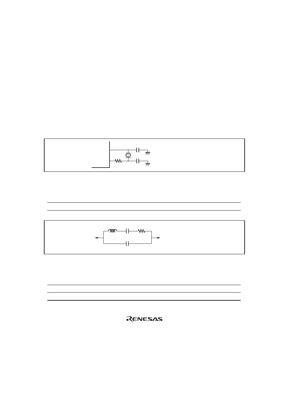
Figure 19.2 shows a typical method of connecting a crystal resonator. An appropriate damping
resistance R
d
, given in table 19.1, should be used. An AT-cut parallel-resonance crystal resonator
should be used.
Figure 19.3 shows the equivalent circuit of a crystal resonator. A resonator having the
characteristics given in table 19.2 should be used.
A crystal resonator with frequency identical to that of the system clock (
φ) should be used.
EXTAL
XTAL
R
d
C
L2
C
L1
C
L1
= C
L2
= 10 to 22 pF
Figure 19.2 Typical Connection to Crystal Resonator
Table 19.1 Damping Resistance Values
Frequency (MHz)
4
8
10
R
d
(
Ω) 500 200 0
XTAL
C
L
AT-cut parallel-resonance crystal resonator
EXTAL
C
0
L
R
s
Figure 19.3 Equivalent Circuit of Crystal Resonator
Table 19.2 Crystal Resonator Parameters
Frequency (MHz)
4
8
10
R
S
(max) (
Ω) 120
80
70
C
0
(max) (pF)
7
7
7