1 pwm setting example, 2 diagram of pwm used as d/a converter – Renesas H8S/2111B User Manual
Page 189
Rev. 1.00, 05/04, page 155 of 544
8.4.1 PWM
Setting
Example
: Pulse added
1-conversion cycle
Combination of the basic pulse and added pulse outputs 0/256 to 255/256 of dudty cycle as low ripple wave form.
Duty cycle
Basic
waveform
Additiona
pulse
0
1
2
3
4
5
6
7
8
9
10
11
12
13
14
15
127/256
128/256
129/256
130/256
PWDR
setting example
H'7F
H'80
H'81
H'82
112 pulses
128 pulses
128 pulses
128 pulses
15 pulses
0 pulses
1 pulse
2 pulses
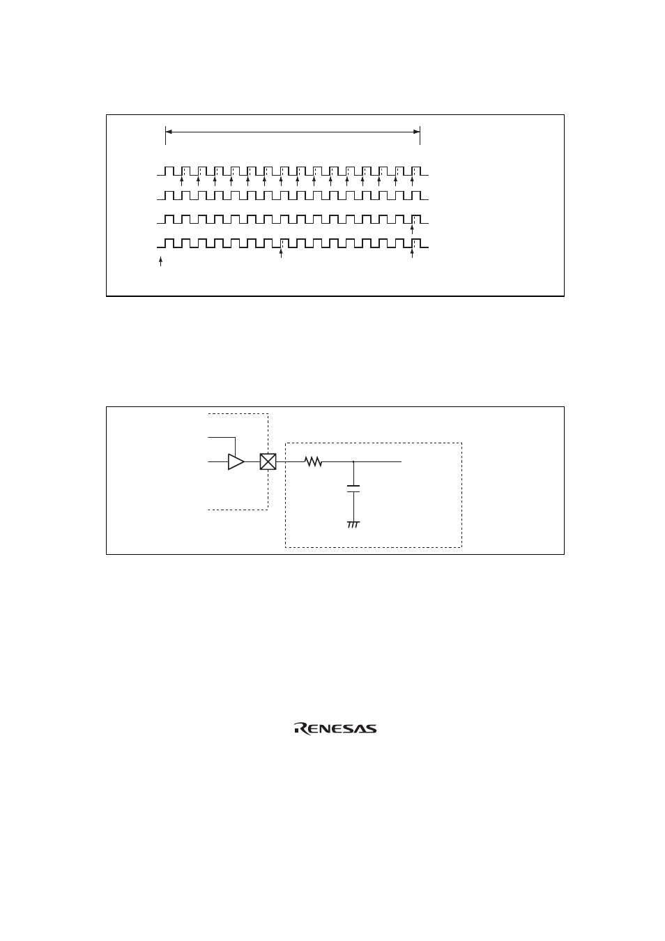
Figure 8.3 Example of PWM Setting
8.4.2
Diagram of PWM Used as D/A Converter
Figure 8.4 shows the diagram example when using the PWM pulse as the D/A converter. Analog
signal with low ripple can be generated by connecting the low pass filter.
This LSI
Low pass filter
Reference value
Resistor : 120 k
Ω
Capacitor : 0.1
µF
Figure 8.4 Example when PWM is Used as D/A Converter