Renesas H8S/2111B User Manual
Page 375
Rev. 1.00, 05/04, page 341 of 544
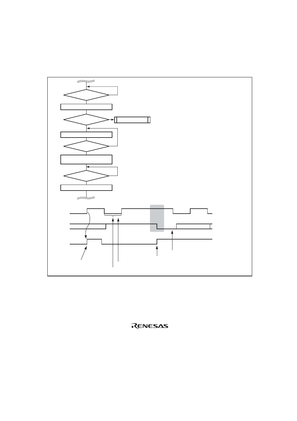
8. Notes on start condition issuance for retransmission
Figure 13.30 shows the timing of start condition issuance for retransmission, and the timing for
subsequently writing data to ICDR, together with the corresponding flowchart. Write the
transmit data to ICDR after the start condition for retransmission is issued and then the start
condition is actually generated.
SDA
IRIC
SCL
[3] (Retransmission) Start condition instruction issuance
[4] IRIC determination
[5] ICDR write (transmit data)
[2] Determination of SCL = Low
[1] IRIC determination
Start condition generation
(retransmission)
IRIC = 1?
Yes
Clear IRIC in ICSR
Read SCL pin
Write transmit data to ICDR
Set BBSY = 1,
SCP = 0 (ICSR)
[1]
[1] Wait for end of 1-byte transfer
[2] Determine whether SCL is low
[3] Issue start condition instruction for retransmission
[4] Determine whether start condition is generated or not
[5] Set transmit data (slave address + R/
W)
[2]
[3]
[4]
[5]
Yes
Yes
No
No
IRIC = 1?
Yes
SCL = Low?
Start condition
issuance?
No
No
Other processing
Note:* Program so that processing from [3] to [5]
is executed continuously.
bit7
ACK
9
Figure 13.30 Flowchart for Start Condition Issuance Instruction for Retransmission and
Timing
Note: This restriction on usage can be canceled by setting the FNC1 and FNC0 bits to 1 in
ICXR.