Figure 285 s, Figure 286 m – Brocade Communications Systems Brocate Ethernet Access Switch 6910 User Manual
Page 1021
Brocade 6910 Ethernet Access Switch Configuration Guide
971
53-1002581-01
Connectivity Fault Management
42
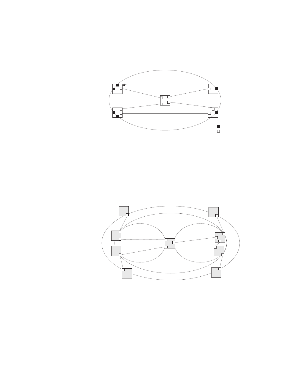
The following figure shows a single Maintenance Domain, with DSAPs located on the domain
boundary, and Internal Service Access Points (ISAPs) inside the domain through which frames may
pass between the DSAPs.
FIGURE 285
Single CFM Maintenance Domain
The figure below shows four maintenance associations contained within a hierarchical structure of
maintenance domains. At the innermost level, there are two operator domains which include
access points marked “O
1
” and “O
2
” respectively. The users of these domains can see their
respective MEPs as well as all the MIPs within their domains. There is a service provider domain at
the second level in the hierarchy. From the service provider’s view, the access points marked “P”
are visible, and all access points within the operator domains have also been made visible as MIPs
according to common practice. And finally, there is a customer domain at the top of the hierarchy.
Users at this level can only see the access points marked “C” on the outer domain boundary. Again,
normal practice is to hide the internal structure of the network from outsiders to reduce security
risks.
FIGURE 286
Multiple CFM Maintenance Domains
Note that the Service Instances within each domain shown above are based on a unique
maintenance association for the specific users, distinguished by the domain name, maintenance
level, maintenance association’s name, and assigned VLAN.
Maintenance Domain
Bridge
DSAP
ISAP
Customer MA
Provider MA
Operator 1 MA
Operator 2 MA
C
C
C
C
O
1
O
1
P
O
2
O
2
P
P
O
1
O
2
P