IAI America ERC3 User Manual
Page 346
Chapter 6
Adjustment of Operation
6.3 I/O Parameter
6.3.1 Positioner Mode 1, Positioner Mode 2 and Pulse
Train Control Mode
336
No.
Situation that requires
adjustment
How to Adjust
Speed is uneven during
the movement
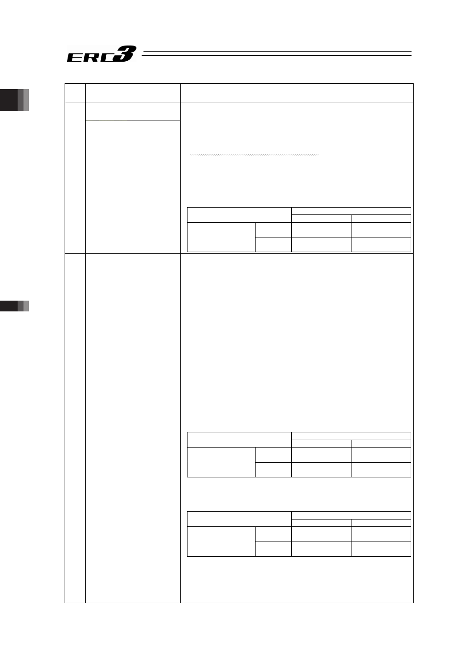
3
Speed accuracy is not
appropriate
Ɣ Increase the value of “Velocity loop proportional gain”. By
setting a larger value, the follow-up ability to the speed
command becomes better.
Setting too large value makes the mechanical components easy
to vibrate. As a reference for the setting, increase the value little
by little by 20% from the initial setting.
For the velocity loop proportional gain parameter, the parameter
number differs depending on the setting of enable/disable of
Gain Scheduling and the high output setting.
Shown below is the table of velocity loop proportional gain
parameter numbers that are enable.
High Output Setting (Parameter No.152)
1 (Enable)
0 (Disable)
101 to
(Enable)
Parameter No.145 Parameter No.145
Gain Scheduling
(Parameter No.144)
to 101
(Disable)
Parameter No.153
Parameter No.31
4 Abnormal noise is
generated.
Especially, when stopped
state and operation in low
speed (less than
50mm/sec),
comparatively high noise
is generated.
Ɣ Input the Parameter No.33 “Torque Filter Time Constant”. Try to
increase by 50 as a reference for the setting. If the setting is too
large, it may cause a loss of control system stability and lead the
generation of vibration.
[Important] Prior to Adjustment:
This phenomenon is likely to occur when the stiffness of the
mechanical components is not sufficient. The actuator itself may
also resonate if its stroke is over 600mm or it is belt-driven type.
Before having an adjustment, check if:
1) Isn’t the setting in Parameter No.7 “Servo Gain Number”,
“Velocity Loop Proportional Gain” or “Velocity Loop Integrated
Gain” described below to extreme?
For the velocity loop proportional gain parameter and the
velocity loop integrated gain parameter, the parameter number
differs depending on the setting of enable/disable of Gain
Scheduling and the high output setting.
2) The stiffness of the load is sufficient as much as possible, or
the attachments are not loosened.
3) The actuator unit is mounted securely with a proper torque.
4) There is no waviness on the actuator mounting surface.
Shown below is the table of velocity loop proportional gain
parameter numbers that are enable.
High Output Setting (Parameter No.152)
1 (Enable)
0 (Disable)
101 to
(Enable)
Parameter No.145 Parameter No.145
Gain Scheduling
(Parameter No.144)
to 101
(Disable)
Parameter No.153
Parameter No.31
Shown below is the table of velocity loop integrated gain
parameter numbers that are enable.
High Output Setting (Parameter No.152)
1 (Enable)
0 (Disable)
101 to
(Enable)
Parameter No.146 Parameter No.146
Gain Scheduling
(Parameter No.144)
to 101
(Disable)
Parameter No.154
Parameter No.32