IAI America ERC3 User Manual
Page 329
Chapter 6
Adjustment of Operation
6.3 I/O Parameter
6.3.1 Positioner Mode 1, Positioner Mode 2 and Pulse
Train Control Mode
319
(23) Velocity loop proportional gain (Parameter No.31)
No.
Name
Symbol
Unit
Input Range
Default factory setting
31
Velocity loop proportional
gain
VLPG
–
1 to 27661
In accordance with
actuator
This becomes enable when the setting of Gain Scheduling (Parameter No.144) and the high
output setting (Parameter No.152) are set disable.
[Refer to 6.2 High Output Setting and Gain Scheduling Function]
This parameter determines the response of the speed control loop. When the set value is
increased, the follow-up ability to the velocity command becomes better (the servo-motor
rigidity is enhanced). The higher the load inertia becomes, the larger the value should be set.
However, excessively increasing the setting will cause overshooting or oscillation, which
facilitates producing the vibrations of the mechanical system.
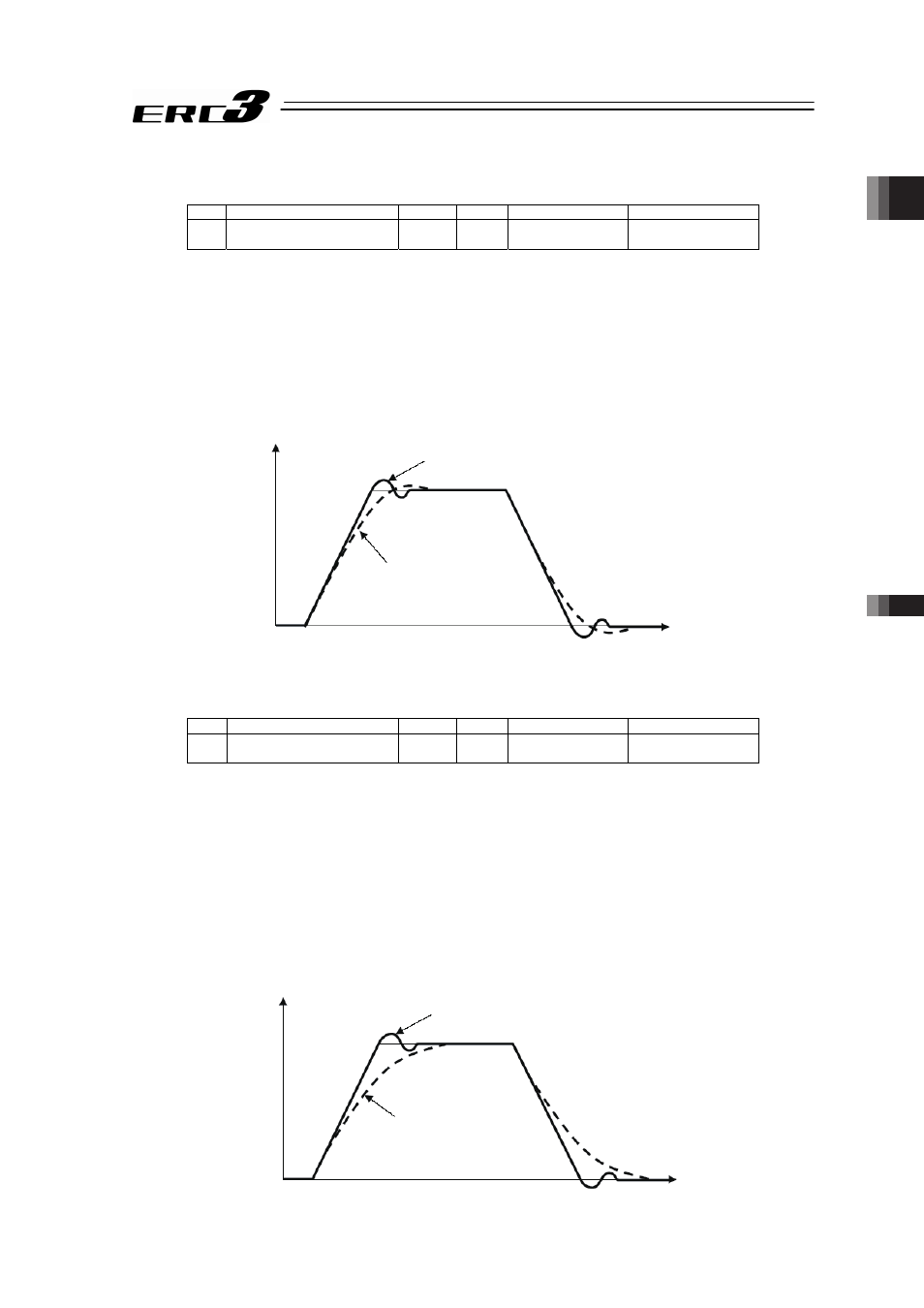
When the set value is high (over-shoot)
When the set value is low
Velocity
Time
(24) Velocity loop integral gain (Parameter No.32)
No.
Name
Symbol
Unit
Input Range
Default factory setting
32 Velocity loop integral gain
VLPT
–
1 to 217270
In accordance with
actuator
This becomes enable when the setting of Gain Scheduling (Parameter No.144) and the high
output setting (Parameter No.152) are set disable.
[Refer to 6.2 High Output Setting and Gain Scheduling Function]
Any machine produces friction. This parameter is intended to cope with deviation generated by
external causes including friction. Increasing the setting value improves the reactive force
against load change. That is, the servo rigidity increases. However, increasing the parameter
value excessively may make the gain too high, which then cause the machine system to be
vibrated due to over-shoot or shaking.
Tune it to obtain the optimum setting by watching the velocity response.
ᴾ
When the set value is high (over-shoot)
When the set value is low
Velocity
Time