Position no.1 position no.2, 5) tension operation image diagram – IAI America ERC3 User Manual
Page 229
Chapter 4 Operation
4.2 Operation in Positioner Mode
4.2.3 Operation in Positioner Mode 2 (Operation Using PIO Converter)
219
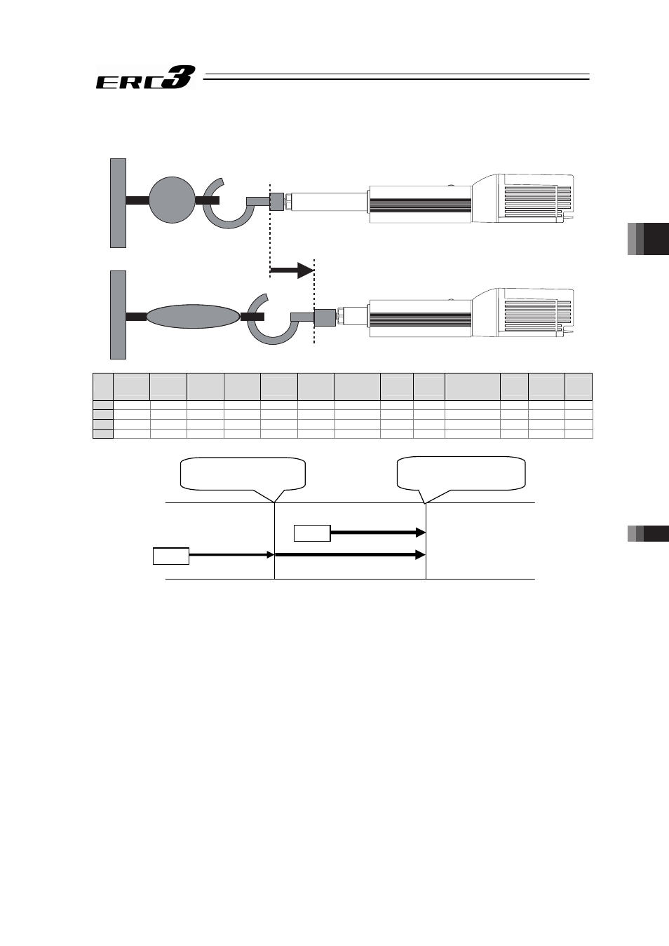
(5) Tension Operation
Image diagram
Position No.1
Position No.2
No.
Position
[mm]
Velocity
[mm/s]
Accele-
ration
[G]
Decele-
ration
[G]
Pressing
[%]
Thresh-
old
[%]
Positioning
width
[mm]
Zone+
[mm]
Zone-
[mm]
Acceleration/
Deceleration
mode
Incre-
mental
Transported
load
Stop
mode
0
1
100.00
250.00
0.20
0.20
0
0
0.10
0.00
0.00
0
0
0
0
2
80.00
250.00
0.20
0.20
50
0
–50.00
0.00
0.00
0
0
0
0
3
CSTR : Start position
Control method
The method of controlling the tension operation is the same as that described in (4) Pressing
operation. The control method is explained below by using the sample position table shown
above.
1) Position No.2 indicates the settings of tension operation. The settings of “Position” and
“Positioning width” show the tension start position and the tension quantity, respectively.
Attach – (minus sign) to the tension quantity. Specify the upper limit of the torque required
for tension in percent (current limit value) in “Pressing”. The speed, acceleration, and
deceleration are the conditions of positioning to the coordinate value (80mm) set in
“Position”.
2) Position No.1 indicates the tension start preparation position. Specify a value larger than
the coordinate value at which the tension provided by position No.2 ends (80 – 50 = 30mm)
in “Position”.
CSTR
Tension Operation
CSTR
Approach Operation
Tension Operation
Tension start position
80mm
Temsion end position
80 – 50 = 30mm