Configuration procedure, N in, Figure 740 – H3C Technologies H3C MSR 50 User Manual
Page 740

355
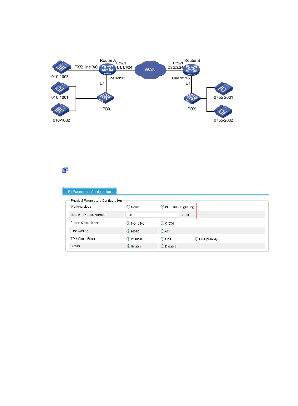
The two routers communicate with their respective PBX by exchanging DSS1 user signaling through an
ISDN interface. The one-stage dialing mode is configured on the two routers.
Figure 740 Network diagram
Configuration procedure
1.
Configure Router A:
# Configure an ISDN PRI group.
Select Voice Management > Digital Link Management from the navigation tree, and then click the
icon of E1 1/1 to access the E1 parameters configuration page.
Figure 741 E1 parameters configuration page
a.
Select the PRI Trunk Signaling option. For other options, use the default settings.
b.
Click Apply.
# Configure local numbers and call routes.
c.
Configure a local number in the local number configuration page: The number ID is 1003, the
number is 0101003, and the bound line is 3/0.
d.
Configure a call route in the call route configuration page: The call route ID is 1001, the
destination number is 0101001, and the trunk route line is 1/1:15. In addition, to select the
Send All Digits of a Called Number option in the Called Number Sending Mode area when you
configure the advanced settings of this call route.
e.
Configure a call route in the call route configuration page: The call route ID is 1002, the
destination number is 0101002, and the trunk route line is 1/1:15. In addition, select the
Send All Digits of a Called Number option in the Called Number Sending Mode area when you
configure the advanced settings of this call route.
