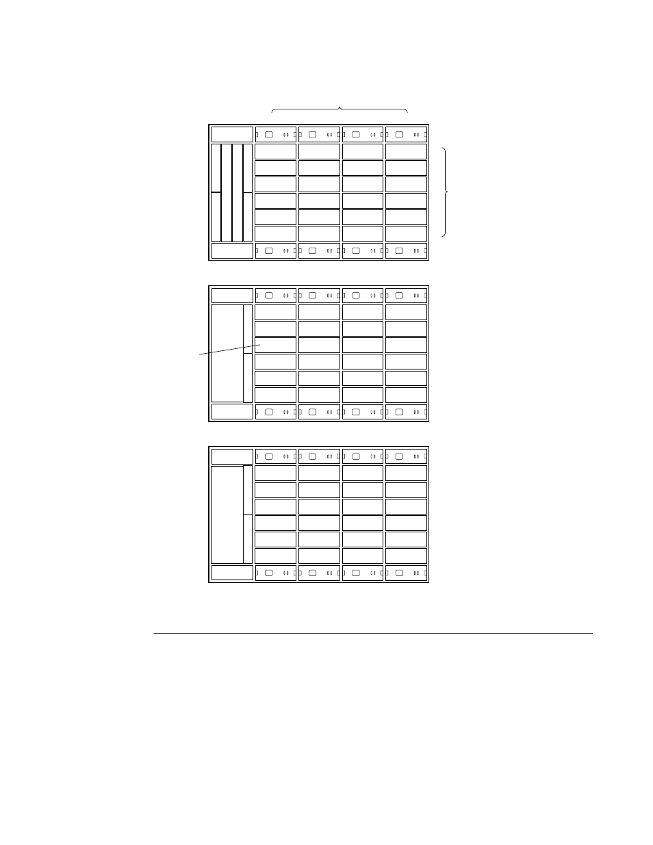
Figure 3–15 ptl addressing in a configuration, Ptl addressing in a configuration –35 – HP Array Controller HSG V8.7 Software User Manual
Page 113
Creat
ing St
ora
gesets
3–
35
Fig
ure 3
–15
PTL Ad
dre
ssi
ng
in a
Con
figu
ration
CXO5851A
Controller A
Controller B
EMU
PVA 0
Cache B
Cache A
10300
10200
10100
10000
20300
20200
20100
20000
30300
30200
30100
30000
40300
40200
40100
40000
50300
50200
50100
50000
60300
60200
60100
60000
12
3
4
5
6
3
2
1
0
EMU
PVA 2
11100
11000
10900
10800
21100
21000
20900
20800
31100
31000
30900
30800
41100
41000
40900
40800
51100
51000
50900
50800
61100
61000
60900
60800
12
3
4
5
6
11
10
9
8
EMU
PVA 3
11500
11400
11300
11200
21500
21400
21300
21200
31500
31400
31300
31200
41500
41400
41300
41200
51500
51400
51300
51200
61500
61400
61300
61200
12
3
4
5
6
15
14
13
12
PTL location =
Device port number = 3
Target number = 08
LUN = 00
Device port numbers
Target
numbers
See also other documents in the category HP Storage:
- StorageWorks MSL6000 Tape Library (61 pages)
- Лент-е накопители HP StoreEver DAT (64 pages)
- Лент-е накопители HP StoreEver DAT (50 pages)
- StoreEver TapeAssure Software (40 pages)
- StoreEver Ultrium Tape Drives (75 pages)
- StoreEver Ultrium Tape Drives (60 pages)
- Linear Tape File System Software (28 pages)
- Linear Tape File System Software (25 pages)
- StoreEver Ultrium Tape Drives (78 pages)
- StoreEver Ultrium Tape Drives (76 pages)
- Linear Tape File System Software (20 pages)
- StoreEver Ultrium Tape Drives (61 pages)
- 2600fx Optical Disk Drive (65 pages)
- Ленточный автозагрузчик HP StorageWorks DAT 72x10 (58 pages)
- StorageWorks 1500cs Modular Smart Array (52 pages)
- StorageWorks 1500cs Modular Smart Array (71 pages)
- 2000fc Modular Smart Array (150 pages)
- StorageWorks 1000 Modular Smart Array (72 pages)
- StorageWorks 1000 Modular Smart Array (81 pages)
- StorageWorks 1500cs Modular Smart Array (48 pages)
- Servidor de almacenamiento HP ProLiant DL585 G2 (152 pages)
- Sistemas de almacenamiento de red HP StorageWorks X3000 (152 pages)
- Software de HP StoreVirtual VSA (127 pages)
- Software de HP StoreVirtual VSA (85 pages)
- X500 Data Vault (331 pages)
- StorageWorks 1000i Virtual Library System (122 pages)
- StorageWorks XP Remote Web Console Software (20 pages)
- 200 Storage Virtualization System (176 pages)
- XP Array Manager Software (101 pages)
- StorageWorks MSA 2.8 SAN Switch (307 pages)
- StorageWorks MSA 2.8 SAN Switch (22 pages)
- StorageWorks MSA 2.8 SAN Switch (104 pages)
- StorageWorks MSA 2.8 SAN Switch (270 pages)
- StorageWorks All-in-One SB600c Storage Blade (72 pages)
- StorageWorks All-in-One SB600c Storage Blade (80 pages)
- StorageWorks All-in-One SB600c Storage Blade (78 pages)
- StorageWorks All-in-One SB600c Storage Blade (60 pages)
- ProLiant DL585 G2 Storage-Server (150 pages)
- Data Protector Express Basic-Software (83 pages)
- Data Protector Express Basic-Software (93 pages)
- ProLiant DL185 G5 Storage Server (174 pages)
- ProLiant High Availability Storage Server (72 pages)
- 2000I G2-Modular-Smart-Array (48 pages)
- P2000 G3 MSA Array Systems (58 pages)
- StorageWorks 2000fc G2 Modular Smart Array (76 pages)