Led indicators, Led indicators on – Brocade Mobility 7131 Access Point Product Reference Guide (Supporting software release 4.4.0.0 and later) User Manual
Page 57
Brocade Mobility 7131 Access Point Product Reference Guide
45
53-1002517-01
2
c. Connect the power supply line cord to the power adapter.
d. Attach the power adapter cable into the power connector on the access point.
e. Plug the power adapter into an outlet.
15. Verify the behavior of the LEDs. For more information, see LED Indicators on page 2-45.
16. Place the ceiling tile back in its frame and verify it is secure.
The access point is ready to configure. For information on an access point default
configuration, see Getting Started on page 3-51. For specific details on system
configurations, see System Configuration on page 4-67.
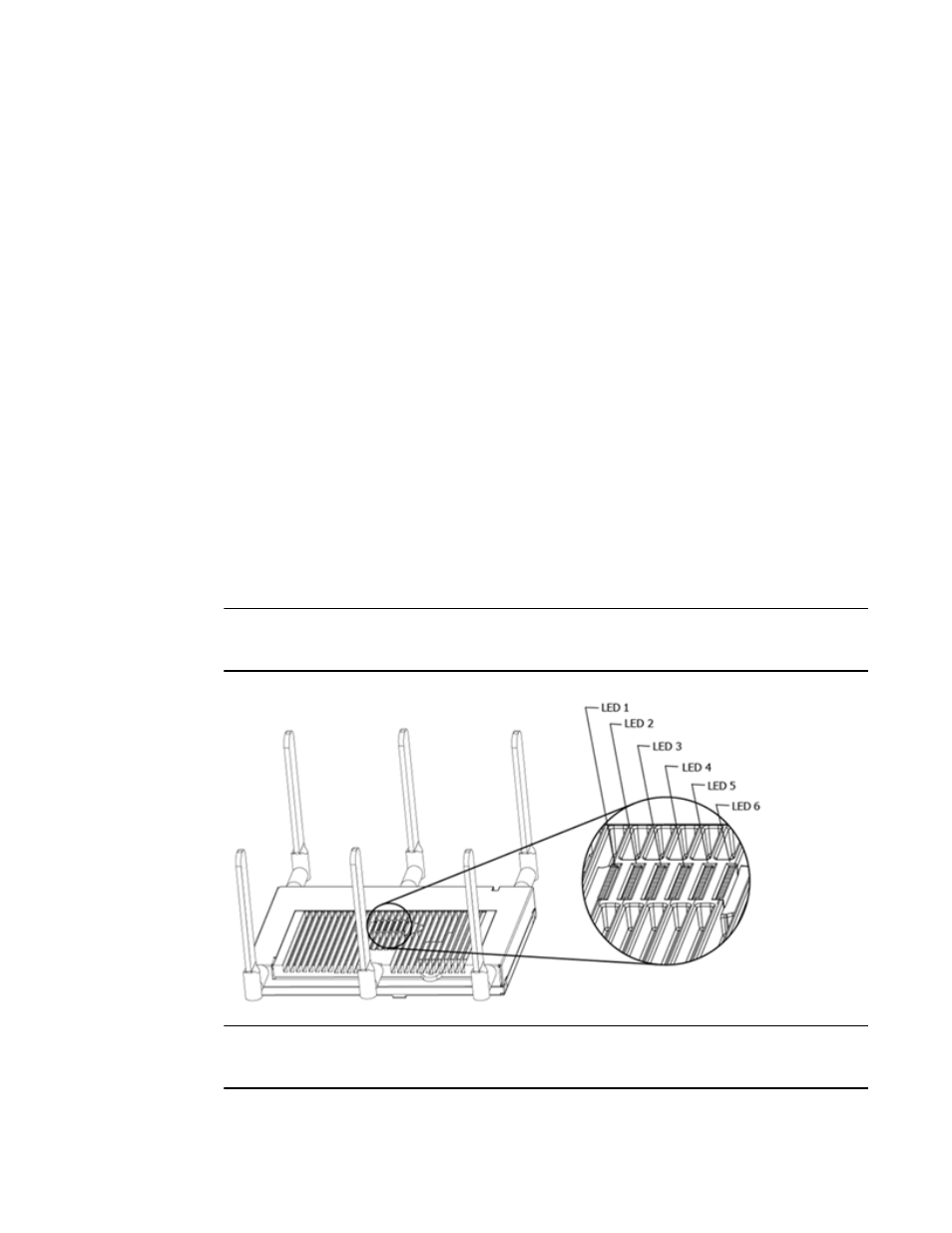
LED Indicators
Both Mobility 7131 and Mobility 7131N model access points have six LEDs on the top of the access
point housing, and one optional LED light pipe at the bottom of the unit. However, a Mobility 7131
Access Point model access point does not use LED 6, as no third radio is available. Five LEDs
illuminate (on top of the housing) for dual radios models and four illuminate for single radio
models.
The access point utilizes two (different colored) lights below each LED. Only one light displays
within a LED at any given time. Every light within each LED is exercised during startup to allow the
user to see if an LED is non-functional. The LEDs turn on and off while rotating around in a circle.
Since two LEDs feed each light pipe, the pattern is from left to right, then right to left.
NOTE
LED blink rate is proportional to activity. The busiest traffic corresponds to the fastest blink, while
the slowest traffic corresponds to slowest blink.
NOTE
Depending on how the 5 GHz and 2.4 GHz radios are configured, the LEDs will blink at different
intervals between amber and yellow (5 GHz radio) and emerald and yellow (2.4 GHz radio).