Screen reference, Pick-lists, Top of the form – Interlogix VEREX Director User Manual
Page 250: Standard
242
Verex Director V4.9.1 User's Guide
21-0381E v4.9.1
Screen Reference
Pick-Lists
(bottom of the Form)
-Panel Group & Panel references (optional): This is
where you select a specific panel-group and panel
in a multi-panel system where the 'tree' is not set to
show items on a panel-by-panel basis. For more
information on this feature, refer to "Other Desktop
Choices".
- Module: This is where you select a module to
view or edit. This area shows a reference
number assigned by the system, and the name
of the selected module, once defined;
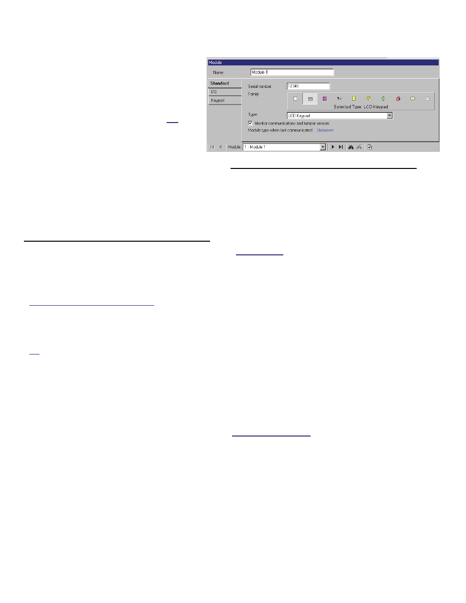
Top of the Form
- Name: A suitable name / location for the module
(up to 30 characters).
Standard
- Serial Number: The actual serial number of the
expansion module. Tip: The serial number is
typically hand-written (5 digits) on a small sticker
on the circuit board.
Converted TDC/PDC Door Controllers: Enter the
'address' of the door controller (as set via jumpers or
switches on the board).
- Family: Select the basic type for the module
you are setting up;
Tip: You can 'hover' your mouse cursor over a symbol
to see a description of what that button represents /
selects.
- Type: Select the specific type/subtype of
module here (where applicable);
- Monitor Communications and Tamper
Sensors: Whether or not module
communications, and the module housing
tamper sensor are to be monitored
(recommended);
- Module type when last communicated:
During each communications session with the
panel, the module types are checked and
displayed here;
I/O
(for modules that support inputs and
outputs)
- Inputs: The number of input points (monitored
sensors) supported by this module;
Note: The first 3 inputs on a system LCD keypad
pertain to the built-in emergency keys rather than
external sensors.
Director
V4.4: Input points associated with newer-
style modules use custom input circuits. (Related
links follow).
Configuration, Input Points, Custom Circuit
Custom Circuit-Types for Input Points
Configuration, Input Points
Input Points—Monitored Sensors
- Outputs: The number of outputs
(programmable electronic switches) on the
device;
Note: Outputs on a "Map" module pertain to firing the
LEDs on the module itself rather than triggering
external devices.
-------------------------
- Input Range: The input point numbers to be
associated with this expansion module.
- Output Range: The range of programmable
output-point numbers to be associated with this
expansion module.
Input and Output Range: The Number-Range for inputs
& outputs is based on the number of inputs and outputs
supported by each module, and the order the modules
are installed--plus the "Display Offset" settings for the
specific panel. For details on the "Display Offset"
value, refer to "System Panels and Displayed Item-
Numbers".
Configuration Modules