INFICON IC6 Thin Film Deposition Controller User Manual
Page 116
5 - 8
PN
07
4-
50
5-
P1
F
IC6 Operating Manual
AGGREGATE RATE CALCULATION EXAMPLE
Displayed Rate = Applied Rate * Master Tooling * Sensor Tooling
Relative Weight = Sensor Weight /
Weights
Contribution Rate = Displayed Rate * Relative Weight
Aggregate Rate =
Contribution Rates. This is the rate that will be displayed on the
Operate screen.
The Displayed Rate is the rate for each sensor displayed on the Sensor Information screen.
It reflects the effects of Master Tooling and Sensor Tooling and is not affected by the Weight
parameter.
Regardless of which sensor fails, the aggregate rate will remain the same.
The following parameters expand from using one sensor when Multipoint is
OFF to using up to eight sensors when Multipoint is turned ON.
(SENSOR) FAILURE ACTION. . Unused (0), PostDp (1), Stop (2),
Suspnd (3), TimePw (4)
Applying the multiplier to all
future aggregate rate results:
Xtal Fail
10
10
4
10
1.25
If during the deposition the use
of the aggregate multiplier is
turned off, the aggregate rate
reverts back to:
Xtal Fail
10
10
4
8
not used
If the layer has not finished, the use of AGGREGATE MULTIPLY may be turned back on and the previously calculated
multiplier (in this case 1.25) will continue to be used.
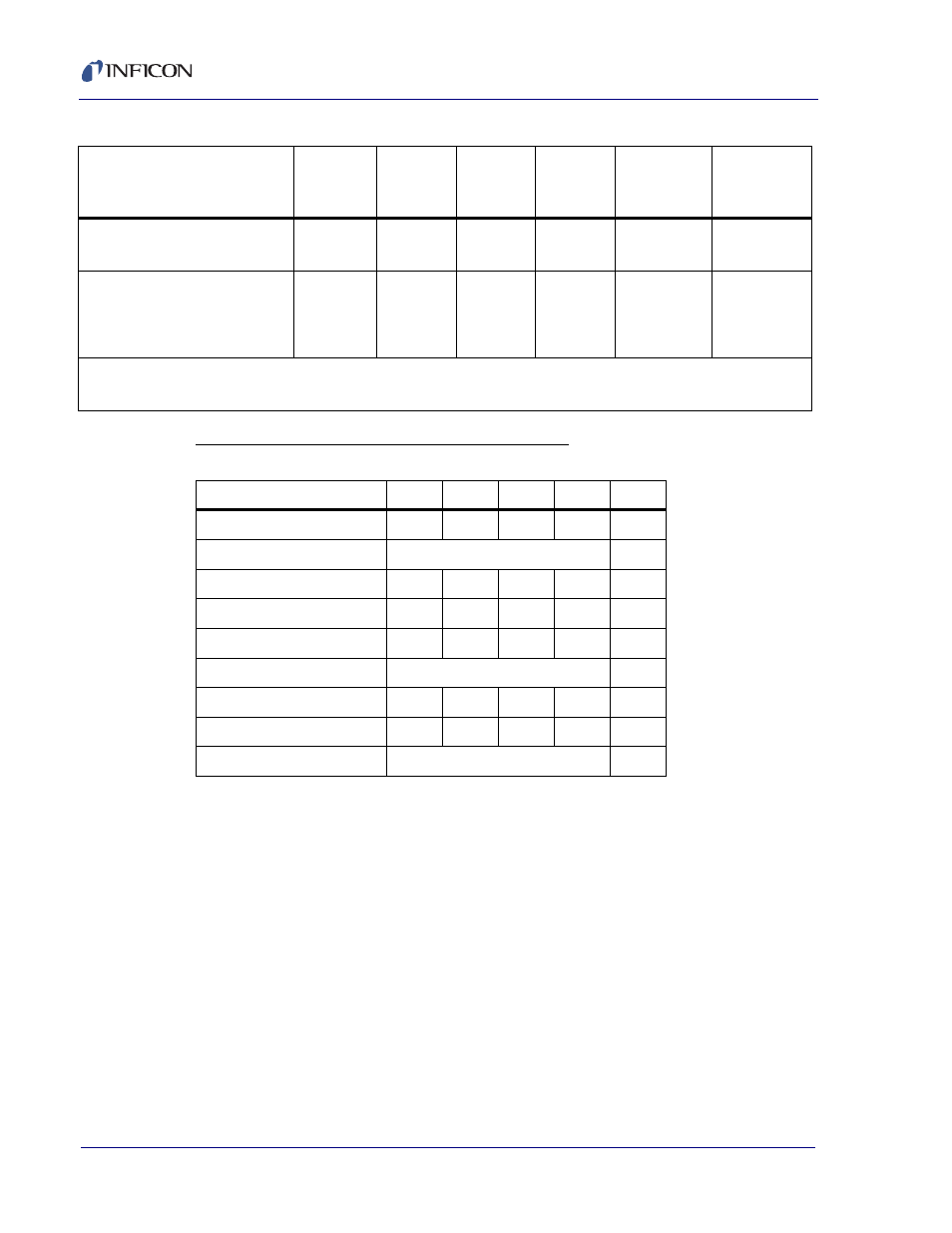
Table 5-1 Aggregate multiplier effect (continued)
Condition of the deposition
Sensor
#1
Rate (Å)
Sensor
#2
Rate (Å)
Sensor
#3
Rate (Å)
Sensor
#4
Rate (Å)
Aggregate
Rate (Å)
Aggregate
Multiplier
Table 5-2 Aggregate rate example data
Sensor
1
2
3
4
Unit
APPLIED RATE
2
4
2.667
1
Å/s
MASTER TOOLING
200
%
SENSOR TOOLING
100
50
75
200
%
DISPLAYED RATE
4
4
4
4
Å/s
SENSOR WEIGHT
50
100
75
25
%
WEIGHTS
250
%
RELATIVE WEIGHT
0.2
0.4
0.3
0.1
N/A
CONTRIBUTION RATE
0.8
1.6
1.2
0.4
Å/s
AGGREGATE RATE
4
Å/s