Pe1 configuration – Brocade Multi-Service IronWare Routing Configuration Guide (Supporting R05.6.00) User Manual
Page 406
378
Multi-Service IronWare Routing Configuration Guide
53-1003033-02
Configuring Multi-VRF
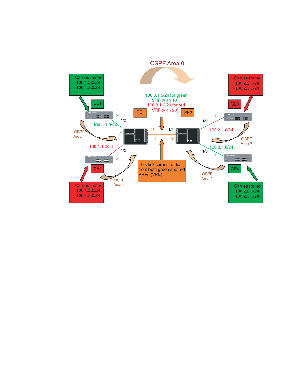
FIGURE 28
OSPF (Area 0) configured between PE1 and PE2 with OSPF (Area 1 and Area 2)
configured between PEs and CEs
The following configuration examples for PE1, PE2, CE1, CE2, CE3, and CE4 describe how to create
the example shown in
PE1 configuration:
In this configuration, VLANs 10 and 20 are created as a link on a tagged port (e 1/10) between PE1
and PE2. Two VRFs (“RED” and “GREEN”) are then defined with each having a unique Route
Distinguisher (RD). VRF “Green” is assigned an RD value of 10:10, and VRF “Red” is assigned an
RD value of 20:20.
Because OSPF is the only routing protocol used in this set-up, multiple OSPF areas are used. Area 0
is configured between the two PEs. Area 1 is configured PE1 and CE’s 1 and 2. Area 0 is configured
between the two PEs. Area 2 is configured PE2 and CE’s 3 and 4.
The virtual Interfaces (ve10 and ve20) are configured with the same IP address (10.3.1.1/24) and
for VRF forwarding in the appropriate VRF (Green or Red). Both are also configured in OSPF Area 0.
Brocade(config)# vlan 10
Brocade(config-vlan-10)# tagged e 1/1
Brocade(config-vlan-10)# router-interface ve 10
Brocade(config-vlan-10)# vlan 20
Brocade(config-vlan-20)# tagged e 1/1
Brocade(config-vlan-20)# router-interface ve 20
Brocade(config-vlan-20)# exit-vrf
Brocade(config)# vrf green
Brocade(config-vrf-green) rd 10:10
Brocade(config-vrf-green) vrf red