Figure 24, Displa, While – Brocade Multi-Service IronWare Routing Configuration Guide (Supporting R05.6.00) User Manual
Page 399: N in
Multi-Service IronWare Routing Configuration Guide
371
53-1003033-02
Overview of Multi-VRF
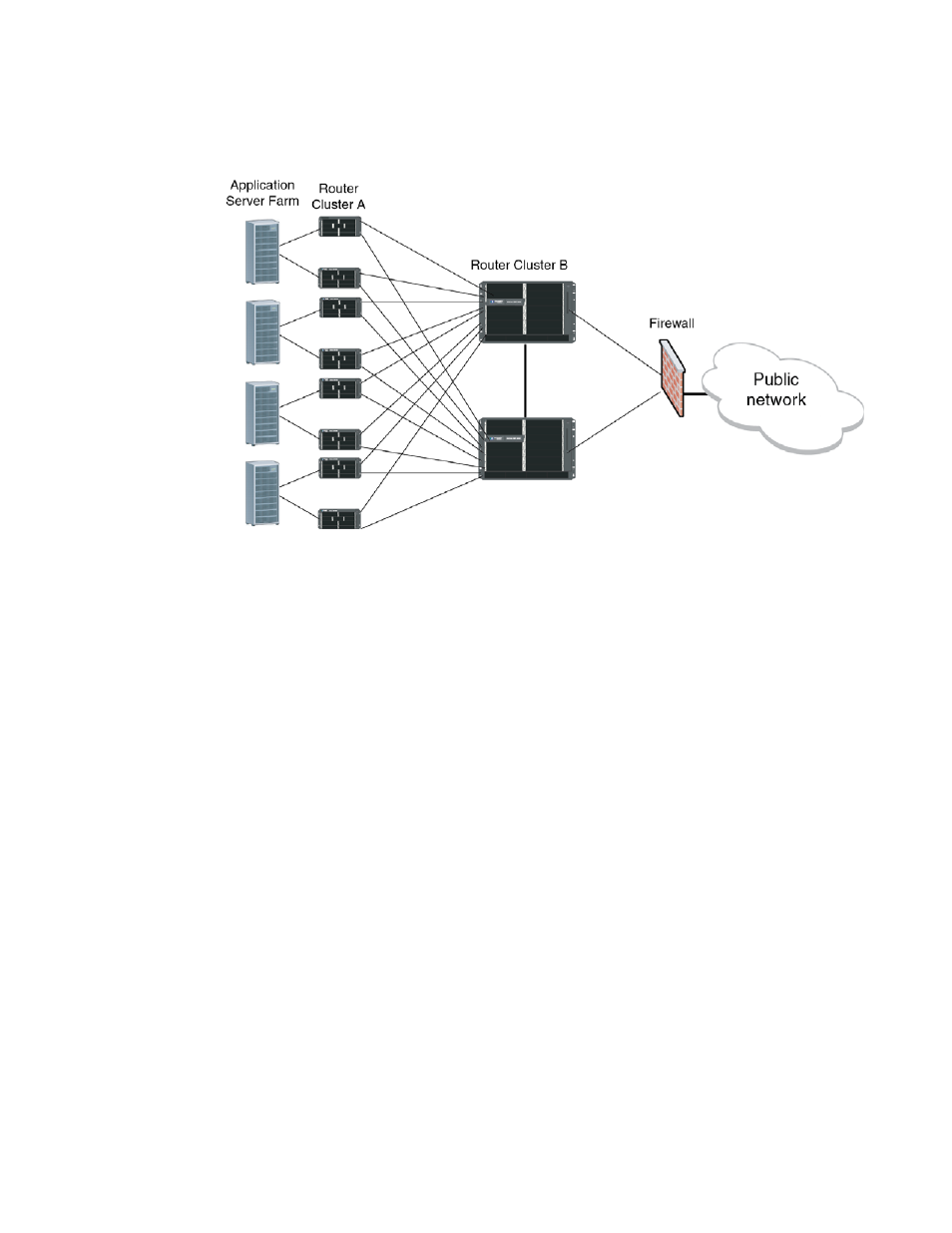
FIGURE 24
Example of Multi-VRF usage in an enterprise data center application
Example of Multi-VRF usage in a service provider network
depicts the use of Multi-VRF in a typical service provider application. This service
provider owns a Layer 2 network connecting the PEs and offers managed VPN services to end
users. As shown in
, a host of PE-CE routing protocols can be used-E-BGP, OSPF, RIP or
Static Routing.
It is also possible that a site (such as site 2) may have several customers in close geographical
proximity as in a business park. This may warrant a dedicated MTU to be placed on-site, which is
owned by the service provider. In such a scenario, the different customers may share the same
MTU and still use overlapping private address spaces. The MTU is a switch that adds a unique
VLAN tag for each connected customer. The PE router (labeled PE2) maps a Layer 3 tagged
interface to a unique VRF. Thus, it could be sharing routes using OSPF with one CE and just using
Static Routing with another CE (both of these may occur over different virtual interfaces on the
same physical interface).
Layer 3 BGP or MPLS VPNs could also be used in a network such as the above. However, if one of
the PE routers does not support MPLS or if the operational staff is not conversant with MPLS
operations, Multi-VRF provides an alternative mechanism to achieve the same objective.