Brocade Multi-Service IronWare Routing Configuration Guide (Supporting R05.6.00) User Manual
Page 209
Multi-Service IronWare Routing Configuration Guide
181
53-1003033-02
Configuring OSPF
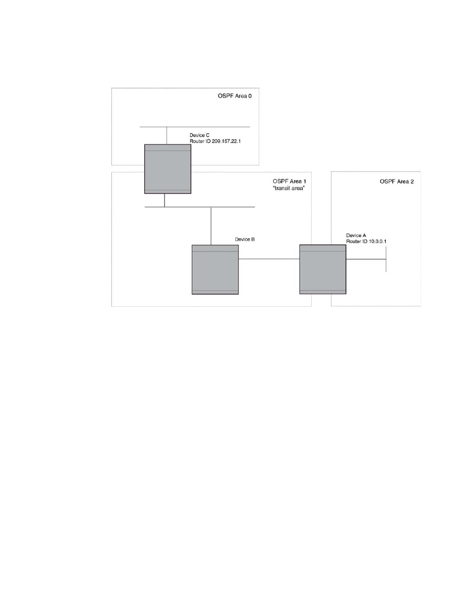
FIGURE 13
Defining OSPF virtual links within a network
Example
shows an OSPF area border router, Device A, that is cut off from the backbone area (area
0). To provide backbone access to Device A, you can add a virtual link between Device A and Device
C using area 1 as a transit area. To configure the virtual link, you define the link on the router that
is at each end of the link. No configuration for the virtual link is required on the routers in the
transit area.
To define the virtual link on Device A, enter the following commands.
Brocade A(config)# router ospf
Brocade A(config-ospf-router)# area 2
Brocade A(config-ospf-router)# area 1
Brocade A(config-ospf-router)# area 1 virtual-link 10.157.22.1
Brocade A(config-ospf-router)# write memory
Enter the following commands to configure the virtual link on Device C.
Brocade C(config)# router ospf
Brocade C(config-ospf-router)# area 0
Brocade C(config-ospf-router)# area 1
Brocade C(config-ospf-router)# area 1 virtual-link 10.0.0.1
Syntax: [no] area ip-addr | num virtual-link router-id
[ authentication-key string | dead-interval num | hello-interval num | retransmit-interval
num | transmit-delay num | md5-authentication key-activation-wait-time num |
md5-authentication key-id num key [0|1] string ]
The area ip-addr | num parameters specify the transit area.