Configuration 1, Pe1 configuration – Brocade Multi-Service IronWare Routing Configuration Guide (Supporting R05.6.00) User Manual
Page 402
374
Multi-Service IronWare Routing Configuration Guide
53-1003033-02
Configuring Multi-VRF
Configuration 1
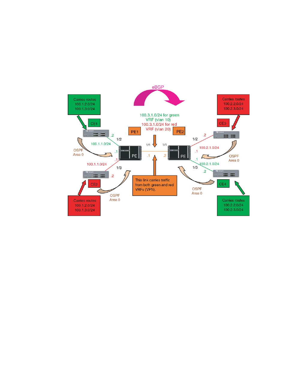
, eBGP is configured between PE1 and PE2 and OSPF (Area 0) is configured
between PEs and CEs.
FIGURE 27
eBGP configured between PE1 and PE2 with OSPF (Area 0) configured between PEs
and CEs
The following configuration examples for PE1, PE2, CE1, CE2, CE3, and CE4 describe how to create
the example shown in
.
PE1 configuration
In this configuration, VLANs 10 and 20 are created as a link on a tagged port (e 1/10) between PE1
and PE2. Two VRFs (“RED” and “GREEN”) are then defined with each having a unique Route
Distinguisher (RD). VRF “Green” is assigned an RD value of 10:10, and VRF “Red” is assigned an
RD value of 20:20.
In the BGP configuration, PE1 is defined in Local AS1. VRFs “Green” and “Red” are configured and
both “Green” and “Red” have the same IP network address assigned (10.3.1.2/24). This is
possible because each of the BGP VRF instances have their own separate BGP tables. This is also
the same IP network address that will be assigned to VRFs “Green” and “Red” on PE2 within Local
AS 2. Redistribution of OSPF routes from PE1’s CE peers is enabled to all for their advertisement to
PE2.
Both VRFs are configured in Area “0” and directed to redistribute their routes to BGP. The physical
interfaces (e 1/2 and e 1/3) to the CEs are assigned to the correct VRF and are configured with the
same IP address (10.1.1.1/24) and OSPF Area “0”.
The virtual Interfaces (ve10 and ve20) are configured with the same IP address (10.3.1.1/24) and
for VRF forwarding in the appropriate VRF (Green or Red).