Volts per hertz – Basler Electric DECS-250N User Manual
Page 83
9440500990 Rev D
67
DECS-250N
Limiters
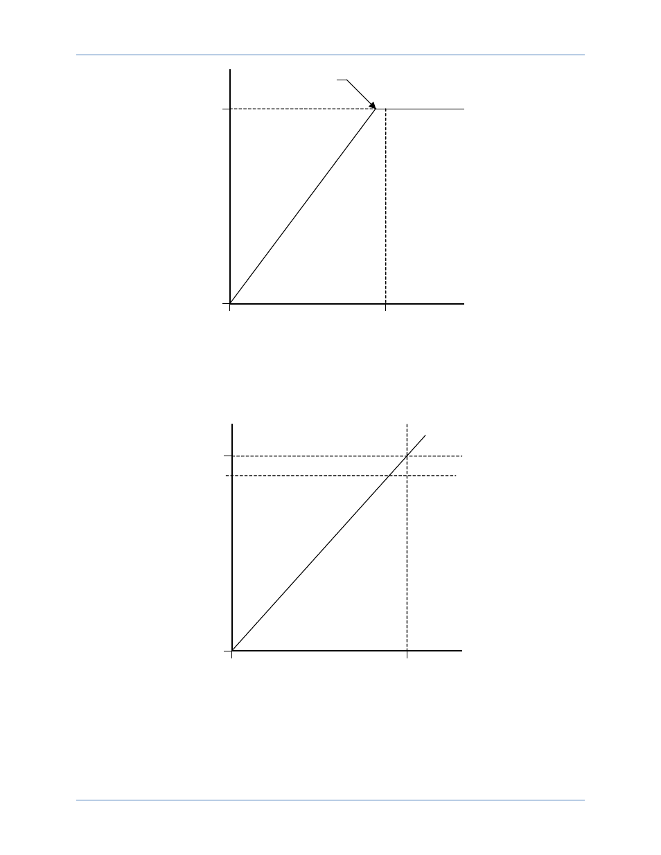
Figure 54. Typical Underfrequency Compensation Curve
Volts per Hertz
The volts per hertz limiter prevents the regulation setpoint from exceeding the volts per hertz ratio defined
by the underfrequency slope setting
C
. A typical volts per hertz limiter curve is illustrated in Figure 55.
Figure 55. Typical 1.1 PU Volts per Hertz Limiter Curve
Beside the underfrequency slope setting, volts per hertz limiter operation is determined by the high limiter
setting, low limiter setting, and time limiter setting. The high limiter setting
D
establishes the maximum
threshold for volts per hertz limiting, the low limiter setting
E
establishes the minimum threshold for volts
per hertz limiting, and the time limiter setting
F
establishes the time delay for limiting.
Corner Frequency
G
E
N
E
R
A
T
O
R
V
O
L
T
S
GENERATOR FREQUENCY
P0004-34.vsd
12-03-01
0 %
100 %
Nominal
10 Hz
V
ol
ts
/H
er
tz
R
at
io
G
E
N
E
R
A
T
O
R
V
O
L
T
S
GENERATOR FREQUENCY
P0004-33.vsd
12-03-01
0 %
110 %
Nominal
0 Hz
100 %