Modbus™ communication, Rs-485 port, Modbus ™ communication – Basler Electric DECS-250N User Manual
Page 180

164
9440500990 Rev D
Communication
DECS-250N
Modbus
™ Communication
BESTCOMSPlus Navigation Path: Settings Explorer, Communications, Modbus Setup
HMI Navigation Path: Not available through HMI.
DECS-250N systems support the RS-485 mode and Modbus/TCP (Ethernet) mode at the same time.
DECS-250N Modbus communication registers are listed and defined in the Modbus Communication
chapter of this manual.
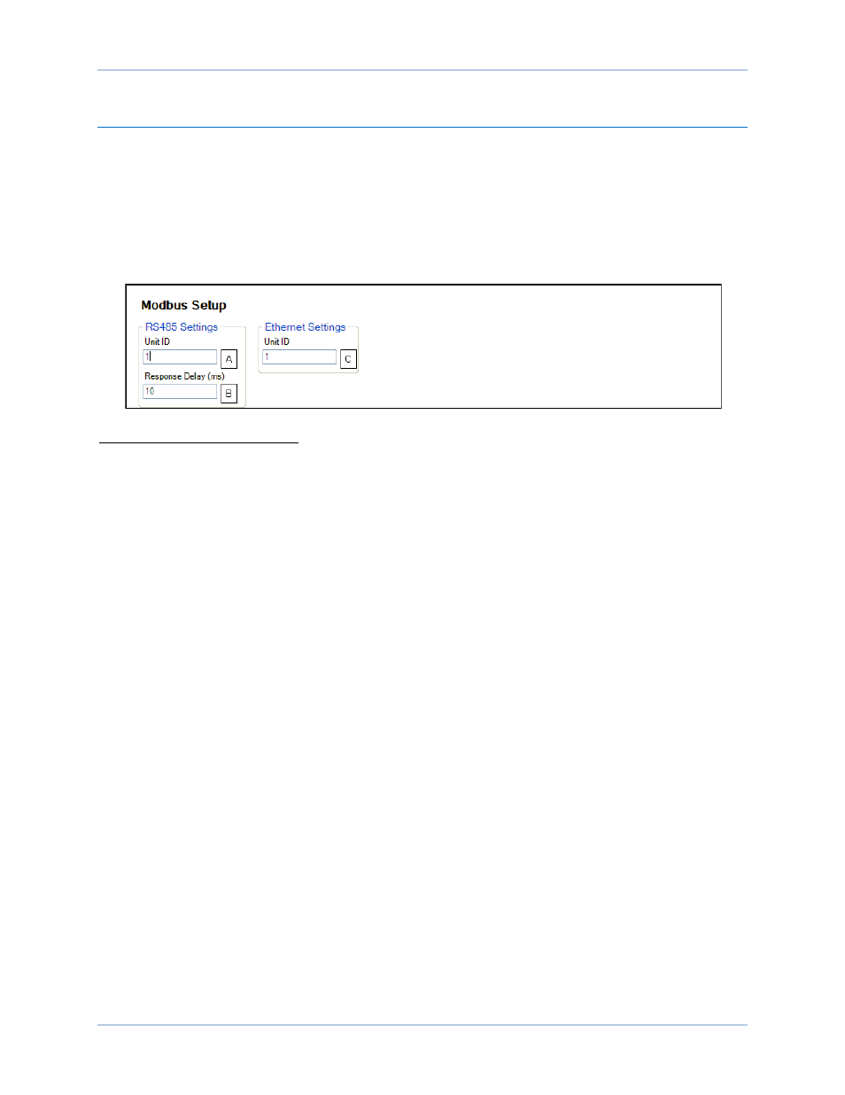
Modbus settings for RS-485 and Ethernet are illustrated in Figure 138 and consist of RS-485 Unit ID
A
,
RS-485 Response Delay
B
, and Ethernet Unit ID
C
.
Figure 138. Modbus Setup
A
RS-485 Unit ID: Adjustable from 1 to 247 in increments of 1.
B
RS-485 Response Delay: Adjustable from 10 to 10,000 ms in 10 ms increments.
C
Ethernet Unit ID: Adjustable from 1 to 247 in increments of 1.
RS-485 Port
BESTCOMSPlus Navigation Path: Settings Explorer, Communications, RS-485 Setup
HMI Navigation Path: Settings, Communications, RS-485 Setup
An RS-485 port uses the Modbus RTU (remote terminal unit) protocol for polled communication with other
networked devices or remote annunciation and control with an IDP-800 Interactive Display Panel. RS-485
port terminals are located on the left side panel and are identified as RS-485 A, B, and C. Terminal A
serves as the send/receive A terminal, terminal B serves as the send/receive B terminal, and terminal C
serves as the signal ground terminal. Figure 139 illustrates typical RS-485 connections for multiple
DECS-250N controllers communicating over a Modbus network.
