Signal input, Test signal characteristics – Basler Electric DECS-250N User Manual
Page 207
9440500990 Rev D
191
DECS-250N
Testing
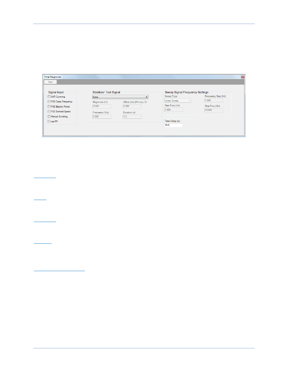
Signal Input
Signal input selections determine the point in the PSS circuitry where the test signal is applied. Test
points include AVR Summing, PSS Comp Frequency, PSS Electric Power, PSS Derived Speed, Manual
Summing, and var/PF.
A time delay is provided to delay the start of a PSS test after the Time Response screen Start button is
clicked.
Figure 161. Time Response Screen
Test Signal Characteristics
Test signal characteristics (magnitude, offset, frequency, and duration) can be adjusted according to the
type of test signal selected.
Magnitude
The test signal magnitude is expressed as a percentage and excludes the gain of externally-applied
signals.
Offset
A dc offset can be applied to the PSS test signal. The offset is expressed as a per-unit value used in
proper context wherever the test signal is applied. A dc offset cannot be applied to a Step test signal.
Frequency
The test signal frequency can be adjusted as desired for Step and Sine test signals. See Swept Sine Test
Signal for information about configuring the frequency attributes of swept sine test signals.
Duration
A duration setting controls the total test duration for Sine and External test signals. For Step test signals,
the duration setting determines the “on” period of the signal. The duration setting does not apply to Swept
Sine signals.
Swept Sine Test Signals
Swept Sine test signals employ a unique set of characteristics that include the sweep style, frequency
step, and start/stop frequencies.
Sweep Type
A Swept Sine test signal can be configured as linear or logarithmic.
Start and Stop Frequencies
The range of a Swept Sine test signal is determined by Start Frequency and Stop Frequency settings.
Frequency Step
The frequency of a Swept Sine test signal is incremented according to the sweep type used. For linear
sweeps, the test signal frequency is incremented by “step” every half-cycle of the system frequency. For