Basler Electric DECS-250N User Manual
Page 104
88
9440500990 Rev D
Event Recorder
DECS-250N
Level Triggers
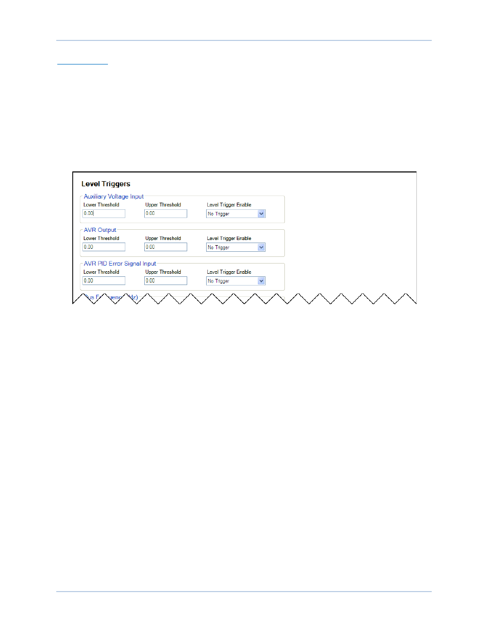
Level triggering initiates a data log based on the value of an internal variable. The variable can be a
minimum or maximum value and can be specified to trigger a record when the monitored variable crosses
a minimum threshold from above, or a maximum threshold from below. A minimum and maximum
threshold may also be selected for the monitored variable, causing the monitored value to trigger a record
when it rises above its maximum threshold or decreases below its minimum threshold.
Level triggers are configured in BESTCOMSPlus on the Level Triggers tab (Figure 82) in the Data Log
area of the Report Configuration. The Level Triggers tab consists of a list of parameters that can be
selected to trigger a data log. Each parameter has a level trigger enable setting which configures
triggering of a data log when the parameter increases above the upper threshold setting or decreases
below the lower threshold setting. The parameters available to trigger a data log are listed below.
Figure 82. Data Log Level Triggers
•
Auxiliary voltage input
•
AVR output
•
AVR PID error signal input
•
Bus frequency
•
Bus voltage
•
Comp. frequency deviation
•
Control output
•
Cross current input
•
Droop
•
FCR error
•
FCR output
•
FCR state
•
Field current
•
Field voltage
•
Frequency response
•
FVR error
•
FVR output
•
FVR state
•
Generator apparent power
•
Generator average current
•
Generator average voltage
•
Generator current Ia
•
Generator current Ib
•
Generator current Ic
•
Generator frequency
•
Generator power factor
•
Generator reactive power
•
Generator real power
•
Generator voltage Vab
•
Generator voltage Vbc
•
Generator voltage Vca
•
Negative sequence current
•
Negative sequence voltage
•
Null balanced level
•
OEL controller output
•
OEL ref.
•
OEL state
•
Internal state
•
Position indication
•
Positive sequence current
•
Positive sequence voltage
•
PSS electrical power
•
PSS filtered mech. power
•
PSS final output
•
PSS lead/lag #1
•
PSS lead/lag #2
•
PSS lead/lag #3
•
PSS lead/lag #4
•
PSS mechanical power
•
PSS mechanical power LP #1
•
PSS mechanical power LP #2
•
PSS mechanical power LP #3
•
PSS mechanical power LP #4
•
PSS post-limit output