Basler Electric DECS-250N User Manual
Page 42
26
9440500990 Rev D
Regulation
DECS-250N
•
The BESTCOMSPlus Control Panel screen (available in the BESTCOMSPlus Metering Explorer)
•
A raise or lower command transmitted through the DECS-250N Modbus port
The range of adjustment is defined by Minimum
J
and Maximum
K
settings that are expressed as a
percentage of the rated field voltage. The length of time required to adjust the FVR setpoint from one limit
to the other is controlled by a Traverse Rate
L
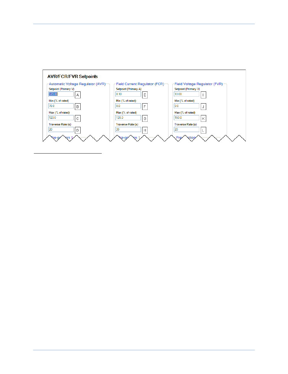
setting. These settings are illustrated in Figure 15.
Figure 15. AVR, FCR, and FVR Regulation Settings
A
AVR Setpoint: Range of adjustment is based on the rated generator voltage and limited by the AVR Min
(B) and Max (C) settings.
B
Min (% of rated): Adjustable from 70 to 120% in 0.1% increments.
C
Max (% of rated): Adjustable from 71 to 120% in 0.1% increments.
D
Traverse Rate (s): Adjustable from 10 to 200 seconds in 1 second increments.
E
FCR Setpoint: Range of adjustment is based on the rated field current and limited by the FCR Min (F)
and Max (G) settings.
F
Min (% of rated): Adjustable from 0 to 120% in 0.1% increments.
G
Max (% of rated): Adjustable from 0 to 120% in 0.1% increments.
H
Traverse Rate (s): Adjustable from 10 to 200 seconds in 1 second increments.
I
FVR Setpoint: Range of adjustment is based on the rated field voltage and limited by the FCR Min (J)
and Max (K) settings.
J
Min (% of rated): Adjustable from 0 to 150% in 0.1% increments.
K
Max (% of rated): Adjustable from 0 to 150% in 0.1% increments.
L
Traverse Rate: Adjustable from 10 to 200 seconds in 1 second increments.
Var
When operating in var mode, the DECS-250N regulates the reactive power (var) output of the generator
based on the var setpoint
A
. The setting range of the var setpoint depends on the generator ratings and
other associated settings. Var setpoint adjustment is made through:
•
Application of contacts at DECS-250N contact inputs configured for raising and lowering the
active setpoint
•
Application of an analog control signal at the Auxiliary Control input
•
The BESTCOMSPlus Control Panel screen (available in the BESTCOMSPlus Metering Explorer)
•
A raise or lower command transmitted through the DECS-250N Modbus port
The range of adjustment is defined by Minimum
B
and Maximum
C
settings that are expressed as a
percentage of the generator rated kVA output. The length of time required to adjust the Var setpoint from
one limit to the other is controlled by a Traverse Rate setting
D
. A Fine Voltage Adjustment Band setting
E
defines the upper and lower boundaries of voltage correction when operating in var or power factor
regulation modes. Var mode settings are illustrated in Figure 16.