Communications, Functional description, Analog inputs – Basler Electric DECS-250N User Manual
Page 344
328
9440500990 Rev D
Analog Expansion Module
DECS-250N
Communications
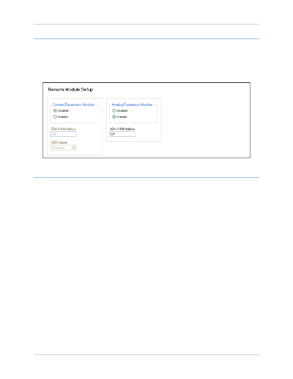
BESTCOMSPlus Navigation Path: Settings, Communications, CAN bus, Remote Module Setup
HMI Navigation Path: Settings, Communication, CAN bus, Remote Module Setup, Analog Expansion
Module
The analog expansion module must be enabled with the correct J1939 address. A Control Area Network
(CAN) is a standard interface that enables communication between the AEM-2020 and the DECS-250N.
The Remote Module Setup screen is illustrated in Figure 176.
Figure 176. Remote Module Setup
Functional Description
Analog Inputs
BESTCOMSPlus Navigation Path: Settings, Programmable Inputs, Remote Analog Inputs
HMI Navigation Path: Settings, Programmable Inputs, Remote Analog Inputs
The AEM-2020 provides eight analog inputs that can annunciate a latching or non-latching alarm. The
analog inputs are always monitored and their status is displayed on the appropriate metering screens. To
make identifying the analog inputs easier, a user-assigned name
A
can be given to each input.
Select the input type
B
. Select the amount of hysteresis
C
needed to prevent rapid switching of the alarm. A
user-adjustable arming delay
D
allows configuration of the analog input threshold monitoring in one of two
ways. (1) When the arming delay is set to zero, threshold monitoring is performed all the time, whether or
not excitation is enabled. (2) When the arming delay is set to a non-zero value, threshold monitoring
begins when the arming delay time has expired after system startup is complete. An out-of-range alarm,
configured on the Alarm Configuration, Alarms screen in BESTCOMSPlus
®
, alerts the user of an open or
damaged analog input wire. When enabled, Stop Mode Inhibit
E
turns off analog input protection when
excitation is stopped.
Ranges must be set for the selected input type. Param Min
F
correlates to Min Input Current
G
or Min Input
Voltage
H
and Param Max
I
correlates to Max Input Current
J
or Max Input Voltage
K
.
Each analog input can be independently configured for over or under mode
L
to annunciate an alarm when
the analog input signal falls beyond the threshold
M
. Alarms are configured on the Alarm Configuration,
Alarms screen in BESTCOMSPlus. A user-adjustable activation delay
N
setting delays alarm annunciation
after the threshold has been exceeded.
The remote analog inputs are incorporated into a BESTlogicPlus programmable logic scheme by
selecting them from the I/O group in BESTlogicPlus. For more details, refer to the BESTlogicPlus chapter.
BESTCOMSPlus settings for remote analog inputs are illustrated in Figure 177. Remote Analog Input #1
is shown.