Fcr and fvr modes, Fcr mode stability settings, Caution – Basler Electric DECS-250N User Manual
Page 120

104
9440500990 Rev D
Stability Tuning
DECS-250N
Caution
PID values calculated by the Auto Tuning function are to be
implemented only after their suitability for the application has been
verified by the user. Incorrect PID numbers can result in poor system
performance or equipment damage.
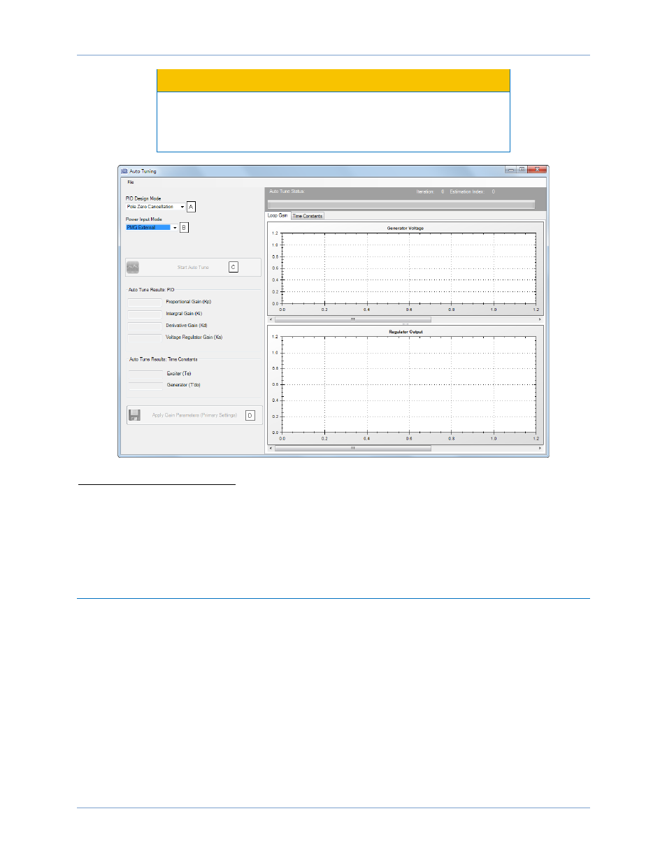
Figure 100. Auto Tuning Window
A
PID Design Mode: Set to either Pole Zero Cancellation or Pole Placement.
B
Power Input Mode: Set to either PMG External or Shunt.
C
Start Auto Tune Button: Begins the auto tuning process.
D
Save PID Gains Button: Saves the calculated PID gains.
The File menu contains options for importing, exporting, and printing a graph (.gph) file.
FCR and FVR Modes
BESTCOMSPlus Navigation Path: Settings Explorer, Operating Settings, Gain, FCR/FVR
HMI Navigation Path: Settings, Operating Settings, Gains, FCR Gains or FVR Gains
Stability tuning can be tailored for optimum performance when operating in field current regulation or field
voltage regulation mode. BESTCOMSPlus FCR stability settings and FVR stability settings are illustrated
in Figure 101.
FCR Mode Stability Settings
The DECS-250N bases its field current output upon the following settings.
The proportional gain (Kp)
A
is multiplied by the error between the field current setpoint and the actual field
current value. Decreasing Kp reduces overshoot in the transient response. Increasing Kp speeds the
transient response.
The integral gain (Ki)
B
is multiplied by the integral of the error between the current setpoint and the actual
field current value. Increasing Ki reduces the time to reach a steady state.
