Avr mode, Fcr mode, Fvr mode – Basler Electric DECS-250N User Manual
Page 50: Var mode, Power factor mode, Summing type
34
9440500990 Rev D
Auxiliary Control
DECS-250N
AVR Mode
In AVR mode, the auxiliary control signal is multiplied by the AVR gain setting
C
. The result defines the
setpoint change as a percentage of the rated generator voltage.
𝐺𝑒𝑛𝑒𝑟𝑎𝑡𝑜𝑟 𝑉𝑜𝑙𝑡𝑎𝑔𝑒 𝐴𝑑𝑗𝑢𝑠𝑡 = 𝑉
𝑎𝑢𝑥
× 0.01 × 𝐴𝑉𝑅 𝐺𝑎𝑖𝑛 × 𝑅𝑎𝑡𝑒𝑑 𝑉𝑜𝑙𝑡𝑎𝑔𝑒
For example, applying +10 Vdc with an AVR gain of 1.0 raises the AVR setpoint 10% of rated generator
voltage. This example also applies to the following modes.
FCR Mode
In FCR mode, the auxiliary control signal is multiplied by the FCR gain setting
D
. The resulting value
relates to a percentage of the rated field current.
𝐹𝐶𝑅 𝐴𝑑𝑗𝑢𝑠𝑡 = 𝑉
𝑎𝑢𝑥
× 0.01 × 𝐹𝐶𝑅 𝐺𝑎𝑖𝑛 × 𝑁𝑜 𝐿𝑜𝑎𝑑 𝑅𝑎𝑡𝑒𝑑 𝐹𝑖𝑒𝑙𝑑 𝐶𝑢𝑟𝑟𝑒𝑛𝑡
FVR Mode
In FVR mode, the auxiliary control signal is multiplied by the FVR gain setting
E
. The resulting value relates
to a percentage of the rated field voltage.
𝐹𝑉𝑅 𝐴𝑑𝑗𝑢𝑠𝑡 = 𝑉
𝑎𝑢𝑥
× 0.01 × 𝐹𝑉𝑅 𝐺𝑎𝑖𝑛 × 𝑁𝑜 𝐿𝑜𝑎𝑑 𝑅𝑎𝑡𝑒𝑑 𝐹𝑖𝑒𝑙𝑑 𝑉𝑜𝑙𝑡𝑎𝑔𝑒
Var Mode
In var mode, the auxiliary control signal is multiplied by the Var gain setting
F
. The resulting value relates to
a percentage of the rated apparent power (kVA).
𝑣𝑎𝑟 𝐴𝑑𝑗𝑢𝑠𝑡 = 𝑉
𝑎𝑢𝑥
× 0.01 × 𝑣𝑎𝑟 𝐺𝑎𝑖𝑛 × 1.7321 × 𝑅𝑎𝑡𝑒𝑑 𝑉𝑜𝑙𝑡𝑎𝑔𝑒 × 𝑅𝑎𝑡𝑒𝑑 𝐶𝑢𝑟𝑟𝑒𝑛𝑡 (𝑂𝑢𝑡𝑒𝑟𝑙𝑜𝑜𝑝 𝑠𝑒𝑙𝑒𝑐𝑡𝑒𝑑)
Power Factor Mode
In Power Factor mode, the auxiliary control signal is multiplied by the PF gain setting
G
to define the PF
setpoint change.
𝑃𝐹 𝐴𝑑𝑗𝑢𝑠𝑡 = 𝑉
𝑎𝑢𝑥
× 0.01 × 𝑃𝐹 𝐺𝑎𝑖𝑛 (𝑂𝑢𝑡𝑒𝑟𝑙𝑜𝑜𝑝 𝑠𝑒𝑙𝑒𝑐𝑡𝑒𝑑)
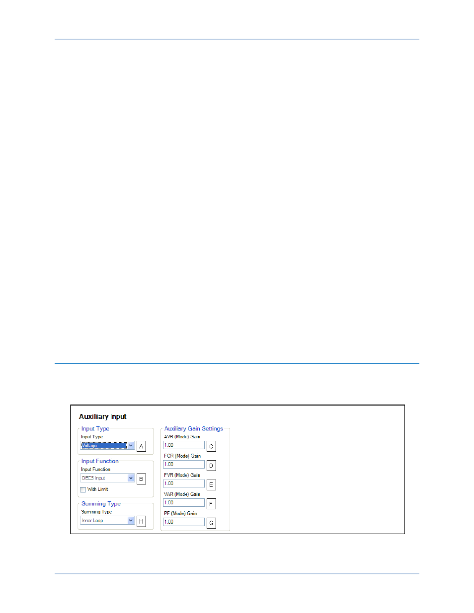
Summing Type
H
The auxiliary control signal can be configured to control the inner or outer regulation control loop.
Selecting the inner loop limits auxiliary control to AVR, FCR, and FVR modes. Selecting the outer loop
limits auxiliary control to PF and Var modes.
Figure 22. Auxiliary Input Settings