Configuration, Generator, field, and bus ratings, Caution – Basler Electric DECS-250N User Manual
Page 187
9440500990 Rev D
171
DECS-250N
Configuration
Configuration
Before the DECS-250N is placed in service, it must be configured for the controlled equipment and
application.
Generator, Field, and Bus Ratings
BESTCOMSPlus Navigation Path: Settings Explorer, System Parameters, Rated Data
HMI Navigation Path: Settings, System Parameters, Rated Data
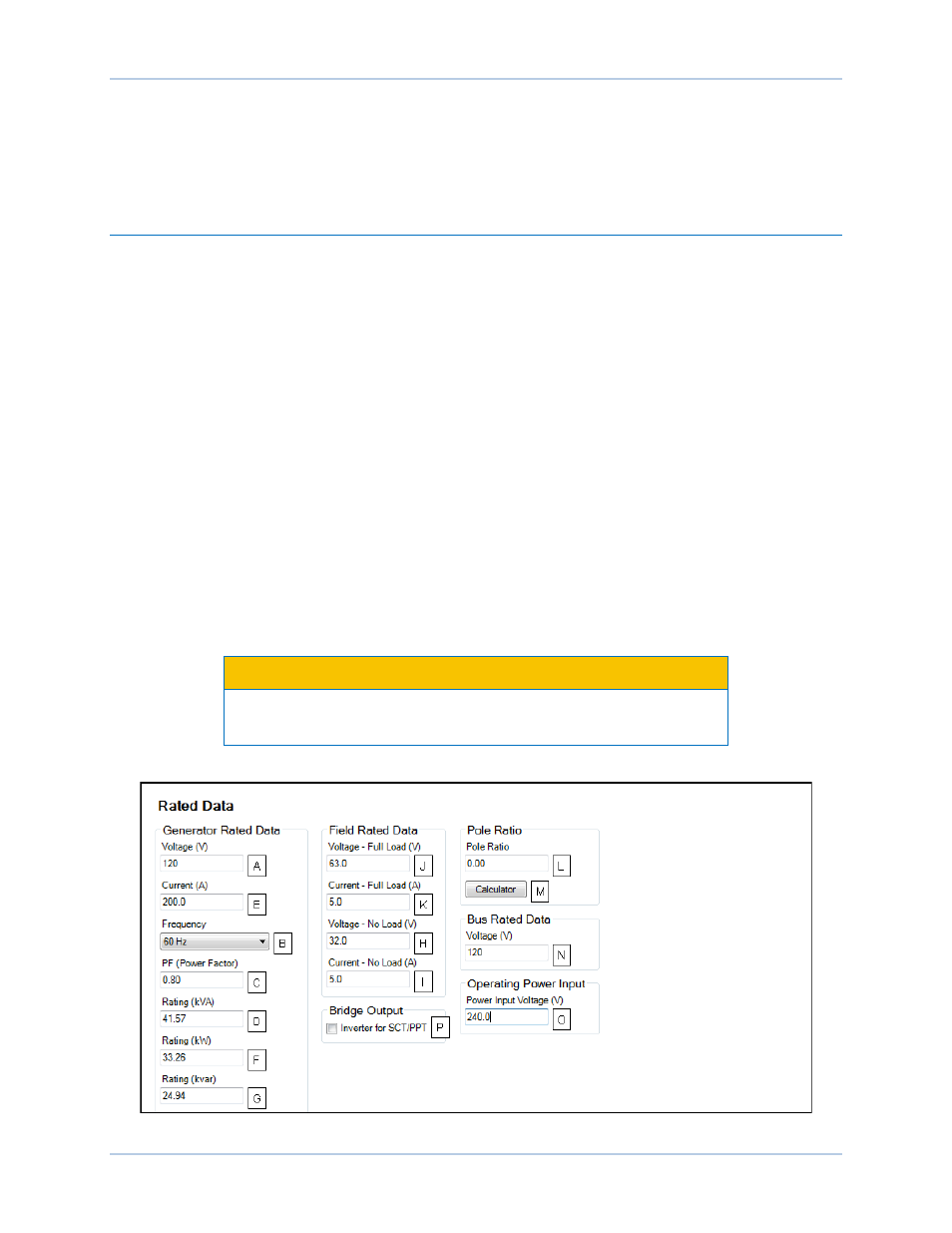
Generator, field, and bus rating settings are illustrated in Figure 149.
For proper excitation control and protection, the DECS-250N must be configured with the ratings of the
controlled generator and field. These ratings are typically shown on the generator nameplate or can be
obtained from the generator manufacturer. Required generator ratings include the voltage
A
, frequency
B
,
power factor
C
, and apparent power
D
(kVA). Generator current
E
,real power
F
(kW), and reactive power
(kvar)
G
are listed with the other generator ratings as read-only settings. These values are automatically
calculated from the other generator ratings entered by the user. Required field ratings include the no load
dc voltage
H
and current
I
and full load voltage
J
and current
K
.
The ratio
L
of exciter poles to generator poles is used by the exciter diode monitor (EDM) function to detect
open and shorted exciter diodes. The calculated value can be entered directly or calculated using the
pole calculator
M
. A minimum ratio of 1.5 is recommended to ensure consistent EDM operation.
In applications where the generator will be synchronized/paralleled with a bus, the DECS-250N must be
configured with the rated bus voltage
N
.
The nominal operating power input voltage
O
is used to calculate the recommended Ka (Loop Gain) value.
This value is also used in metering calculations.
When using the DECS-250N with an exciter requiring an inverted output, check this box
P
to enable the
inverting of the DECS-250N control output.
Caution
Enabling inverted bridge output with an exciter which does not require
inverted bridge output will result in equipment damage.
Figure 149. Generator, Bus, Field, and Pole Ratio Ratings