Nd figure 97 – Basler Electric DECS-250N User Manual
Page 115
9440500990 Rev D
99
DECS-250N
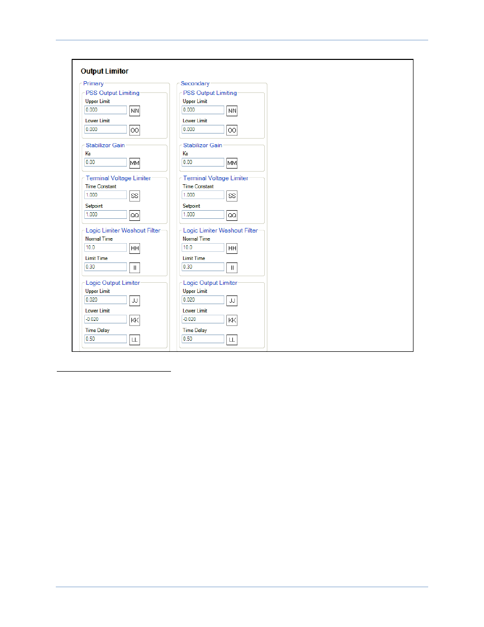
Power System Stabilizer
Figure 97. PSS Output Limiter Settings
A
PSS Control: Select Check box to enable.
B
Supervisory Function Power-On Threshold: Adjustable from 0 to 1 in 0.01 increments.
C
Supervisory Function Power Hysteresis: Adjustable from 0 to 1 in 0.01 increments.
D
Setting Group Logic: Check box to enable.
E
Power Level Threshold: Adjustable from 0 to 1 in 0.01 increments.
F
Power Level Hysteresis: Adjustable from 0 to 1 in 0.01 increments.
G
High-Pass Filtering/Integration Time Constant Tw1: Adjustable from 1 to 20 in 0.01 increments.
H
High-Pass Filtering/Integration Time Constant Tw2: Adjustable from 1 to 20 in 0.01 increments.
I
Speed Low-Pass Filter Switch SSW 0: Select Enabled or Disabled.
J
Low-Pass/Ramp Tracking Time Constant Tl1: Adjustable from 1 to 20 in 0.01 increments.
K
Rotor Frequency Calculation – Quadrature Xq: Adjustable from 0 to 5 in 0.001 increments.
L
Power Washout Filter #2 Software Switch SSW 1: Select Enabled or Disabled.
M
High-Pass Filtering/Integration Time Constant Tw3: Adjustable from 1 to 20 in 0.01 increments.
N
High-Pass Filtering/Integration Time Constant Tw4: Adjustable from 1 to 20 in 0.01 increments.
O
High-Pass Filtering/Integration Inertia (H): Adjustable from 1 to 25 in 0.01 increments.
P
Low-Pass/Ramp Tracking Time Constant Tl2: Adjustable from 1 to 20 in 0.01 increments.
Q
Power Input Gain Stage Kpe: Adjustable from 0 to 2 in 0.01 increments.
R
Low-Pass/Ramp Tracking Time Constant Tl3: Adjustable from 0.05 to 0.2 in 0.01 increments.
S
Low-Pass/Ramp Tracking Time Constant Tr: Adjustable from 0.05 to 1 in 0.01 increments.
T
Low-Pass/Ramp Tracking Exponent Numerator: Adjustable from 0 to 1 in increments of 1.
U
Low-Pass/Ramp Tracking Exponent Denominator: Adjustable from 1 to 5 in increments of 1.
V
PSS Signal Software Switch SSW 2: Select Frequency or Der. Speed.
W
PSS Signal Software Switch SSW 3: Select Power or Der. Freq/Speed.