Synchronizer, Generator synchronization, Frequency correction – Basler Electric DECS-250N User Manual
Page 33: Voltage correction
9440500990 Rev D
17
DECS-250N
Synchronizer
Synchronizer
DECS-250N controllers with a style number of xxxxAxx are equipped with an automatic synchronizer that
acts to align the voltage, phase angle, and frequency of the generator with the bus. The synchronizer
function includes compensation settings for the generator breaker and bias control settings for the
generator governor. Related synchronizer features include voltage matching and bus condition detection.
Generator Synchronization
BESTCOMSPlus Navigation Path: Settings Explorer, Synchronizer/Voltage Matching, Synchronizer
HMI Navigation Path: Settings, Sync/Voltage Matching, Synchronizer
Two modes of generator synchronization are available: phase lock loop and anticipatory
A
. In either mode,
the DECS-250N matches the voltage, phase angle, and frequency of the generator with the bus and then
connects the generator to the bus by closing the generator breaker. Anticipatory mode has the added
capability of compensating for the breaker closing time. (Breaker closing time is the delay between the
issuance of a breaker close command and closure of the breaker contacts.) The DECS-250N
compensates for the breaker closure time by monitoring the frequency difference between the generator
and bus and calculating the advance phase angle required to close the breaker at a zero-degree phase
angle.
Frequency Correction
Generator frequency correction is defined by the slip frequency and further refined by the breaker closing
angle. The slip frequency setting
B
establishes the maximum allowable deviation of the generator speed
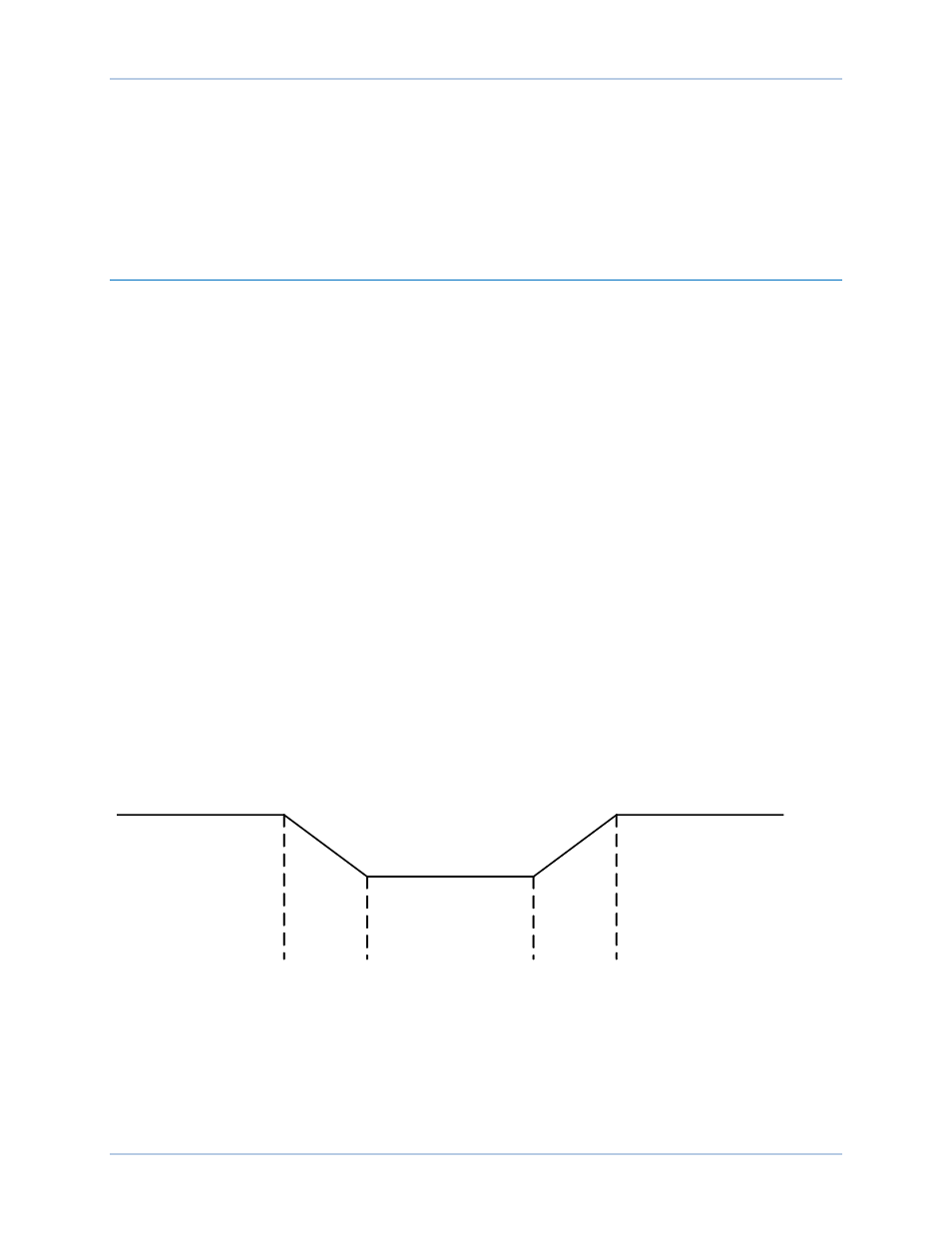
(frequency) from the bus frequency. The Min Slip Control Limit setting
C
and Max Slip Control Limit setting
D
are used to calculate the slip frequency error and to provide continuous slip frequency control while in
phase lock synchronization. If the slip frequency magnitude is above the Max Slip Control Limit, the error
is set equal to the Max Error in the opposite polarity. If the slip frequency magnitude is below the Min Slip
Control Limit, the error is set equal to the Max Error in the opposite polarity. When it is between the two
limits, the error is zero (0). Slip frequency error is shown in Figure 9.
To minimize the impact on the bus during synchronization, the generator frequency can be forced to
exceed the bus frequency
E
at the moment of breaker closure. If this is the case, the DECS-250N will drive
the generator frequency higher than the bus frequency before closing the breaker. The breaker closing
angle setting
F
defines the maximum allowable phase angle difference between the generator and bus. For
breaker closure to be considered, the slip angle must remain within this setting for the duration of the sync
activation delay
G
.
Figure 9. Slip Frequency Error
Voltage Correction
Voltage correction is initiated when the generator voltage is outside the defined voltage window. The
voltage window setting
H
is expressed as a percentage of the bus voltage and determines the band of
generator voltage surrounding the bus voltage where breaker closure will be considered. Enabling the
Vgen>Vbus setting
I
causes the DECS-250N to drive the generator voltage higher than the bus voltage
prior to synchronizing. A generator to bus PT matching level
J
setting is provided to compensate for step-
up or step-down transformers in the system. The DECS-250N adjusts the sensed generator voltage by
Slip Error
= Max (-)
Slip Error
= Max (+)
Slip Error = 0
P0064-49