Bode plotting, Transfer function – Basler Electric DECS-250N User Manual
Page 205
9440500990 Rev D
189
DECS-250N
Testing
BESTCOMSPlus will sweep the range of frequencies and obtain the corresponding magnitude and phase
responses.
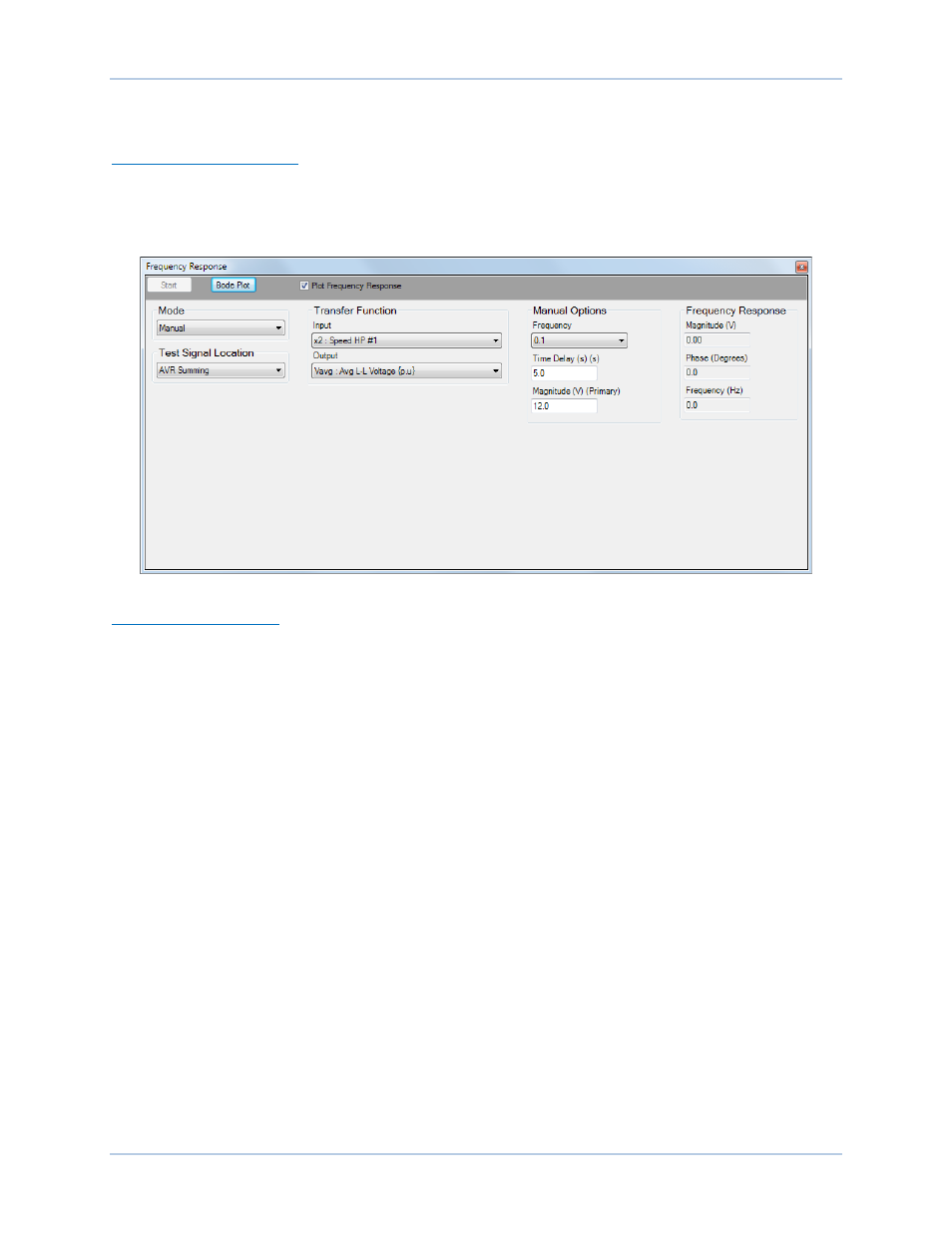
Manual Test Mode Options
Manual test mode options include settings to select the frequency and magnitude of the applied test
signal. A time delay setting selects the time after which the magnitude and phase response corresponding
to the specified frequency is computed. This delay allows transients to settle before computations are
made.
Figure 160. Frequency Response Screen
Auto Test Mode Options
Automatic test mode options include settings to select the minimum frequency, maximum frequency, and
magnitude of the sinusoidal wave that is applied during a frequency response test.
Bode Plotting
A Bode plot can be printed, opened, and saved in graph (.gph) format.
Transfer Function
The point in the DECS-250N logic circuitry where a signal is injected for analysis of magnitude and phase
responses is selectable. Signal points include PSS Comp Frequency, PSS Electric Power, AVR
Summing, AVR PID Input, and Manual PID Input.
The type of input signal to be injected and output point are selectable, and include:
•
AvrOut
•
B Hz: Bus Frequency {Hz}
•
CntOp: Control Output {pu}
•
CompF: Compensated Frequency
Deviation
•
Droop
•
ErrIn: AVR Error Signal
•
FcrErr
•
FcrOut
•
FcrState
•
FvrErr
•
FvrOut
•
FvrState
•
G Hz: Generator Frequency {Hz}
•
I1: Positive Sequence Current {pu}
•
I2: Negative Sequence Current {pu}
•
Ia: Phase A Current {pu}
•
Iaux: Cross Current Input {pu}
•
Iavg: Ave Line Current{pu}
•
Ib: Phase B Current {pu}
•
Ic: Phase C Current {pu}
•
Ifd: Field Current {pu}
•
kVA: Total Power {pu}
•
kvar: Reactive Power {pu}
•
kW: Real Power {pu}
•
MechP: Filtered Mechanical Power
•
Network Load Share
•
NullBalance: Null Balance Level