Speed signal, Rotor frequency calculation, Generator electrical power signal – Basler Electric DECS-250N User Manual
Page 109: Pss frequency input signal
9440500990 Rev D
93
DECS-250N
Power System Stabilizer
Speed Signal
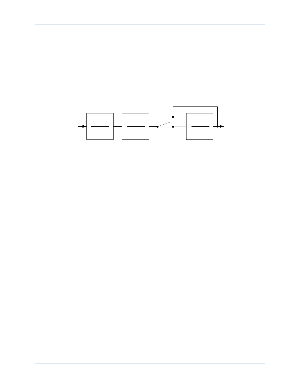
The speed signal is converted to a constant level that is proportional to the shaft speed (frequency).
Two high-pass (frequency washout) filter stages are applied to the resulting signal to remove the average
speed level and produce a speed deviation signal. This ensures that the stabilizer reacts only to changes
in speed and does not permanently alter the generator terminal voltage reference.
The frequency washout filter stages are controlled by time constant settings Tw1
G
and Tw2
H
. Low-pass
filtering of the speed deviation signal can be enabled or disabled through software switch SSW 0
I
. The
low-pass filter time constant is adjusted by the TI1 setting
J
.
Figure 86 shows the high-pass and low-pass filter transfer function blocks in frequency domain form. (The
letter s is used to represent the complex frequency of Laplace operator.)
Figure 86. Speed Signal
Rotor Frequency Calculation
During steady-state conditions, the terminal frequency of the generator is a good measure of rotor speed.
However, this may not be the case during low frequency transients, due to the voltage drop across the
machine reactance. To compensate for this effect, the DECS-250N first calculates the terminal voltages
and currents. It then adds the voltage drop across the quadrature reactance to the terminal voltages to
obtain internal machine voltages. These voltages are then used to calculate the rotor frequency. This
gives a more accurate measure of rotor speed during low frequency transients when stabilizing action is
required.
The quadrature axis compensation used in the rotor frequency calculation is entered through the
Quadrature Xq setting
K
.
Generator Electrical Power Signal
Figure 87 illustrates the operations performed on the power input signal to produce the integral of
electrical power deviation signal.
The generator electrical power output is derived from the generator VT secondary voltages and generator
CT secondary currents applied to the DECS-250N.
The power output is high-pass (washout) filtered to produce the required power deviation signal. If
additional washout filtering is desired, a second high-pass filter can be enabled by software switch SSW
1
L
. The first high-pass filter is controlled by time constant setting Tw3
M
and the second high-pass filter is
controlled by time constant setting Tw4
N
.
PSS Frequency Input Signal
SSW 0
Enable
Disable
Washed Out
Speed
Compensated
Frequency
P0026-13
sT
w1
1+ sT
w1
sT
w2
1+ sT
w2
1
1+ sT
l1