Takeover oel, Figure 43 – Basler Electric DECS-250N User Manual
Page 74
58
9440500990 Rev D
Limiters
DECS-250N
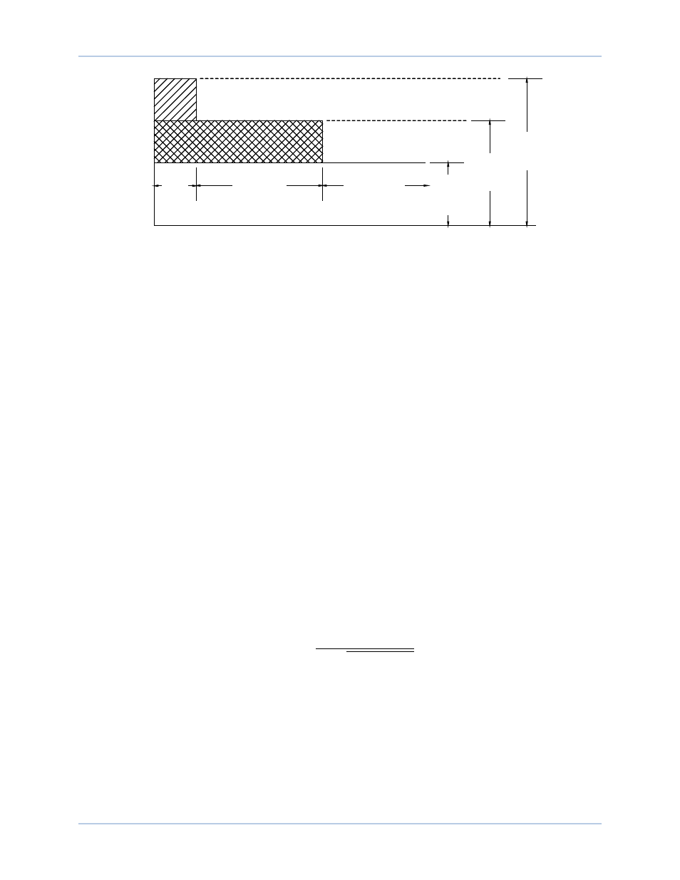
Figure 43. Summing Point, Online, Overexcitation Limiting
The online, low-level OEL threshold is determined by the low-level setting
F
. When the excitation level is
below the low-level setting, no action is taken by the DECS-250N. The generator is permitted to operate
indefinitely with this level of excitation. When the excitation level exceeds the low-level setting for the
duration of the medium time setting, the DECS-250N acts to limit the excitation to the value of the low-
level setting.
The online, medium-level OEL threshold is determined by a medium level
G
and medium time
H
setting.
When the excitation level exceeds the medium level setting, the DECS-250N acts to limit the excitation to
the value of the medium-level setting. If this level of excitation persists for the duration of the high time
setting, the DECS-250N acts to limit the excitation to the value of the medium-level setting.
The online, high-level OEL threshold is determined by a high level
I
and high time
J
setting. When the
excitation level exceeds the high level setting, the DECS-250N instantaneously acts to limit the excitation
to the value of the medium-level setting.
OEL Voltage Dependency
Online OEL operation can be tailored for fault proximity by enabling
K
the OEL voltage dependency
function. If a fault is close to the generator, the OEL high-level setting is disabled (based upon the rate of
change) and switches to the medium-level setting. If a fault is away from the machine, all three (high,
medium, and low) settings remain active. In other words, if the rate of terminal voltage reduction exceeds
the OEL voltage dependency setting
L
, the high-level setting remains enabled. Otherwise, the high-level
setting is disabled.
Takeover OEL
Takeover overexcitation limiting limits the field current level in relation to an inverse time characteristic
similar to that shown in Figure 44. Separate curves may be selected for online and offline operation. If the
system enters an overexcitation condition, the field current is limited and forced to follow the selected
curve. The inverse time characteristic is defined by Equation 11.
𝑡
𝑝𝑖𝑐𝑘𝑢𝑝
=
𝐴 × 𝑇𝐷
𝐵 + √𝐶 + 𝐷 × 𝑀𝑂𝑃
Equation 11. Inverse Pickup Time Characteristic
Where:
t
pickup
= time to pick up in seconds
A
= -95.908
B
= -17.165
C
= 490.864
D
= -191.816
TD
= time dial setting <0.1, 20>
MOP = multiple of pickup <1.03, 205>
F
IE
L
D
C
U
R
R
E
N
T
TIME IN SECONDS
High
Current
Time
0-10sec
CONTINUOUS
P0063-10
Medium
Current
Time
0-120sec
Low
Current
Level
Medium
Current
Level
High
Current
Level