N figure 94, figure 95 – Basler Electric DECS-250N User Manual
Page 113
9440500990 Rev D
97
DECS-250N
Power System Stabilizer
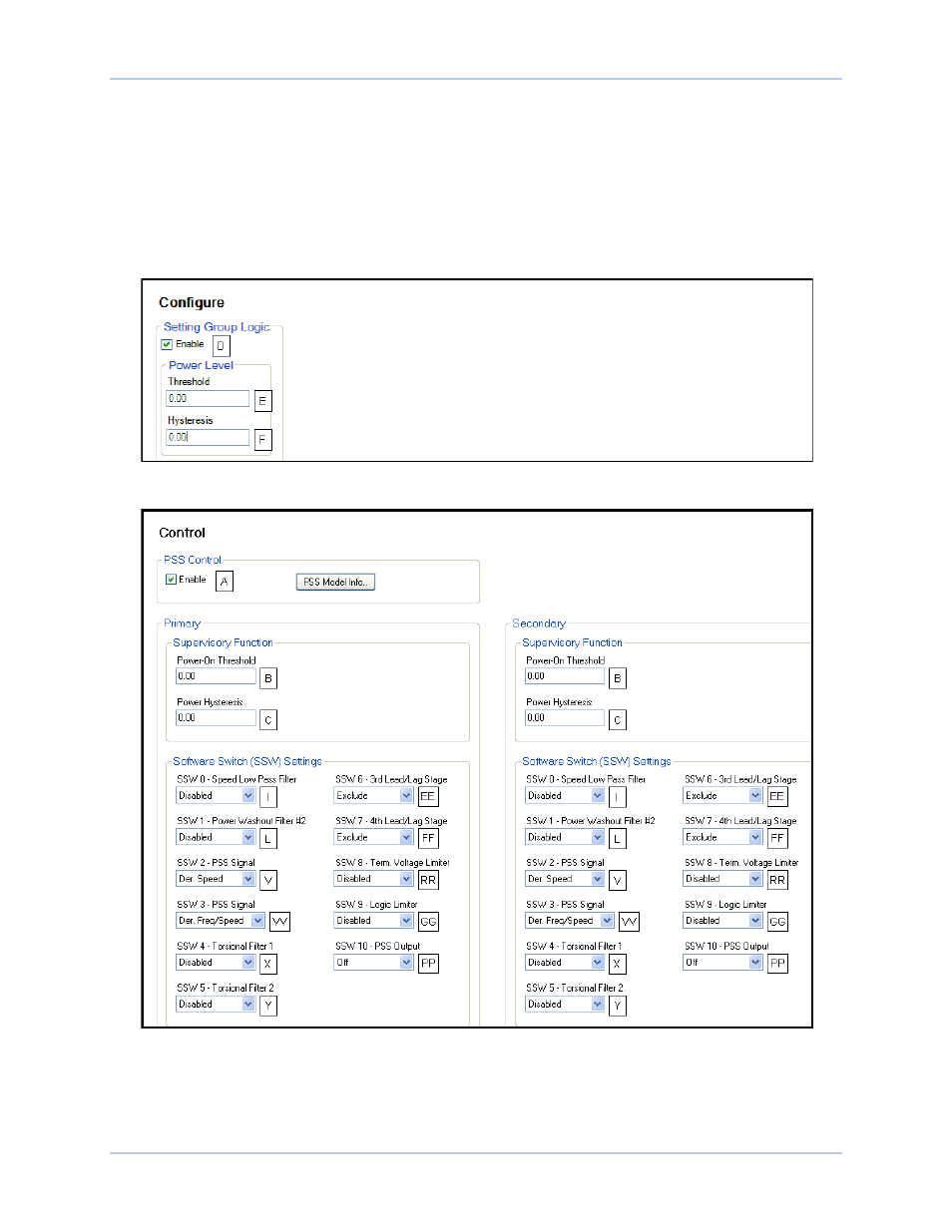
generator voltage exceeds the terminal voltage setpoint
. The terminal voltage limiter is enabled and
disabled by software switch SSW 8
RR
. The limit setpoint is normally selected such that the limiter will
eliminate any contribution from the PSS before the timed overvoltage or volts per hertz protection
operates.
The limiter reduces the stabilizer’s upper limit, V
PSS_ULMT
, at a fixed rate until zero is reached or overvoltage
is no longer present. The limiter does not reduce the AVR reference below its normal level; it will not
interfere with system voltage control during disturbance conditions. The error signal (terminal voltage
minus the limit start point) is processed through a conventional low-pass filter to reduce the effect of
measurement noise. The low-pass filter is controlled by a time constant
SS
.
Figure 94. PSS Configuration Settings
Figure 95. PSS Control Settings