External analog input connections – Basler Electric DECS-250N User Manual
Page 340
324
9440500990 Rev D
Analog Expansion Module
DECS-250N
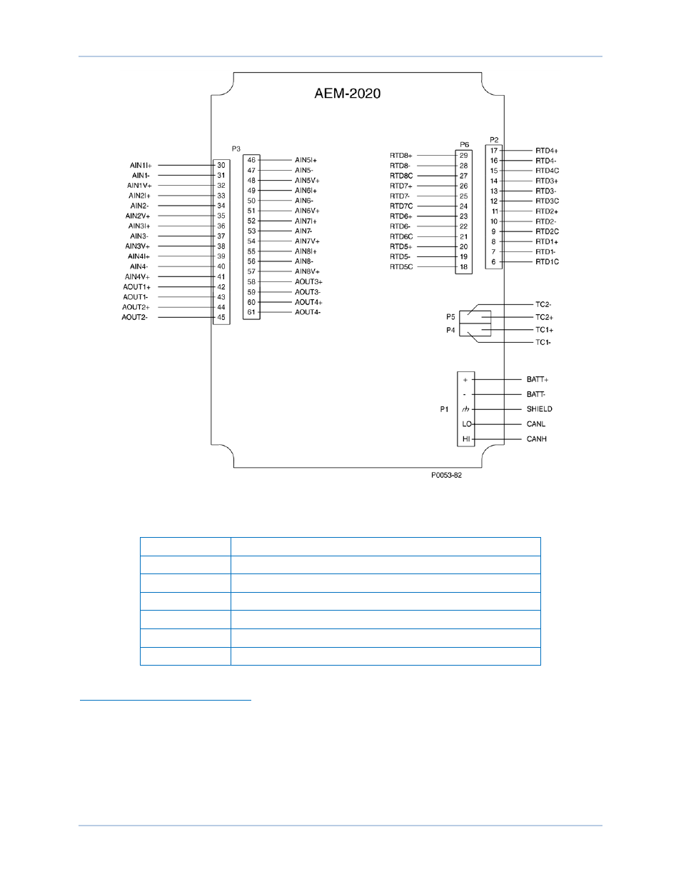
Figure 169. Input and Output Terminals
Table 43. Input and Output Terminals
Connector
Description
P1
Operating Power and CAN bus
P2
RTD Inputs 1 - 4
P3
Analog Inputs 1 - 8 and Analog Outputs 1 - 4
P4
Thermocouple 1 Input
P5
Thermocouple 2 Input
P6
RTD Inputs 5 - 8
External Analog Input Connections
Voltage input connections are shown in Figure 170 and current input connections are shown in Figure
171. When using the current input, AIN V+ and AIN I+ must be tied together.
This manual is related to the following products: