Derived mechanical power signal, Stabilizing signal selection, Pss power input signal – Basler Electric DECS-250N User Manual
Page 110
94
9440500990 Rev D
Power System Stabilizer
DECS-250N
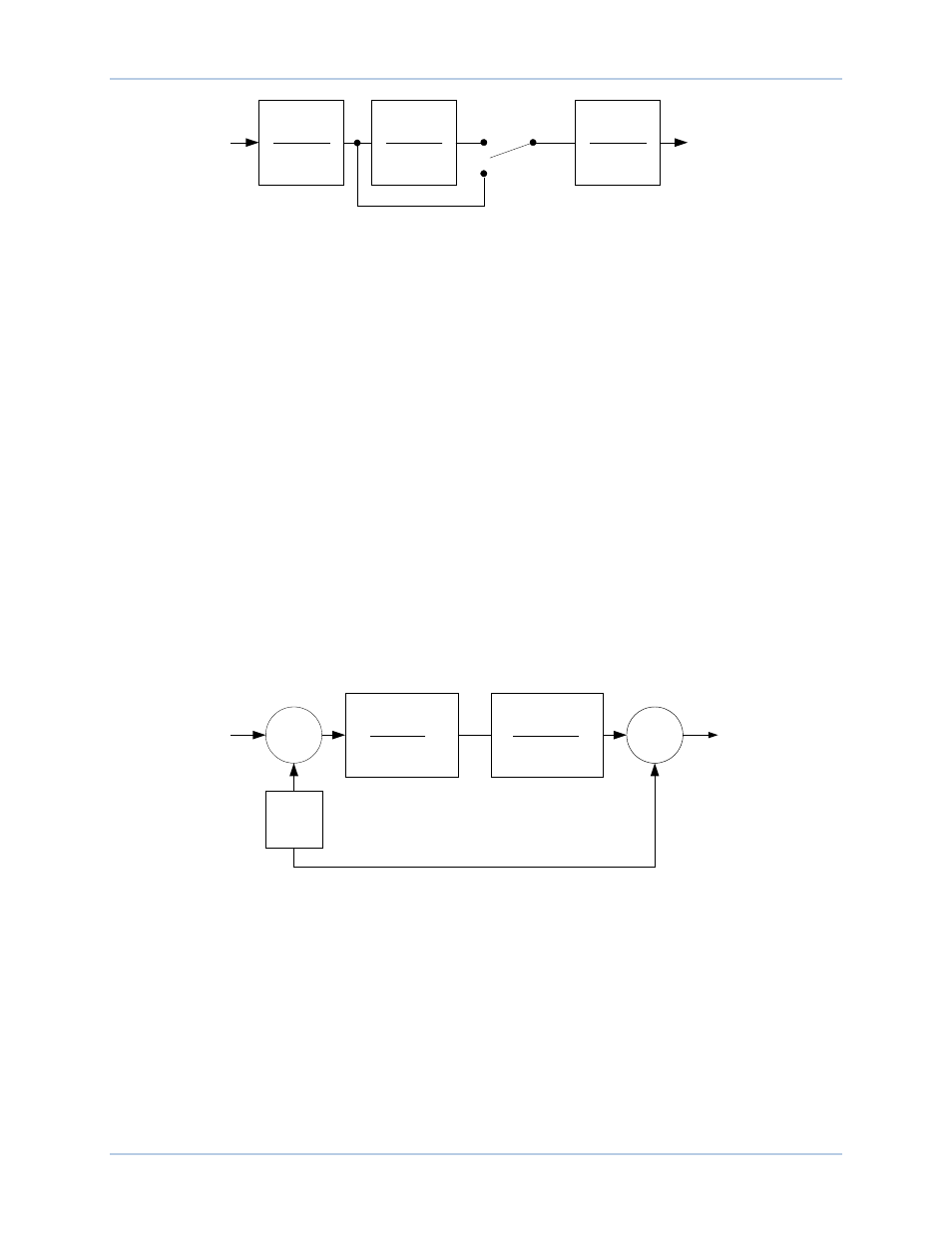
Figure 87. Generator Electrical Power Signal
After high-pass filtering, the electrical power signal is integrated and scaled, combining the generator
inertia constant
O
(2H) with the speed signal. Low-pass filtering within the integrator is controlled by time
constant TI2
P
.
Derived Mechanical Power Signal
The speed deviation signal and integral of electrical power deviation signal are combined to produce a
derived, integral of mechanical power signal.
An adjustable gain stage, Kpe
Q
, establishes the amplitude of the electrical power input used by the PSS
function.
The derived integral of mechanical power signal is then passed through a mechanical-power, low-pass
filter and ramp tracking filter. The low-pass filter is controlled by time constant TI3
R
and provides
attenuation of torsional components appearing in the speed input path. The ramp tracking filter produces
a zero, steady-state error to ramp changes in the integral of electric power input signal. This limits the
stabilizer output variation to very low levels for the mechanical power rates of change that are normally
encountered during operation of utility-scale generators. The ramp tracking filter is controlled by time
constant Tr
S
. An exponent consisting of a numerator
T
and denominator
U
is applied to the mechanical
power filter.
Processing of the derived integral of mechanical power signal is illustrated in Figure 88.
Figure 88. Derived Mechanical Power Signal
Stabilizing Signal Selection
Figure 89 illustrates how software switches SSW 2
V
and SSW 3
W
are used to select the stabilizing signal.
Derived speed deviation is selected as the stabilizing signal when the SSW 2 setting is Derived Speed
and the SSW 3 setting is Derived Frequency/Speed. Washed out speed is selected as the stabilizing
signal when the SSW 2 setting is Frequency and the SSW 3 setting is Derived Frequency/Speed.
Washed out power is selected as the stabilizing signal when the SSW 3 setting is Power. (When the SSW
3 setting is Power, the SSW 2 setting has no effect.)
SSW 1
Disable
Enable
Power
Washed Out
Power
P0026-14
sT
w3
1+ sT
w3
sT
w4
1+ sT
w4
T
l2
/ 2H
1+ sT
l2
PSS Power Input Signal
Σ
Σ
+
+
K
PE
Washed
Out
Speed
Derived
Speed
Deviation
P0026-15
(
)
N
M
L
sT
−
+
3
1
1
N
L
R
sT
sT
+
+
3
1
1