Var limiter, Limiter scaling – Basler Electric DECS-250N User Manual
Page 81
9440500990 Rev D
65
DECS-250N
Limiters
Var Limiter
BESTCOMSPlus Navigation Path: Settings Explorer, Operating Settings, Limiters, var
HMI Navigation Path: Settings, Operating Settings, Limiters, VAR
The var limiter can be enabled
A
to limit the level of reactive power exported from the generator. Primary
and secondary setting groups provide additional control for two distinct machine operating conditions. The
var limiter setpoint
B
is expressed as a percentage of the calculated, maximum VA rating for the machine.
A delay setting
C
establishes a time delay between when the var threshold is exceeded and the DECS-
250N acts to limit the var flow.
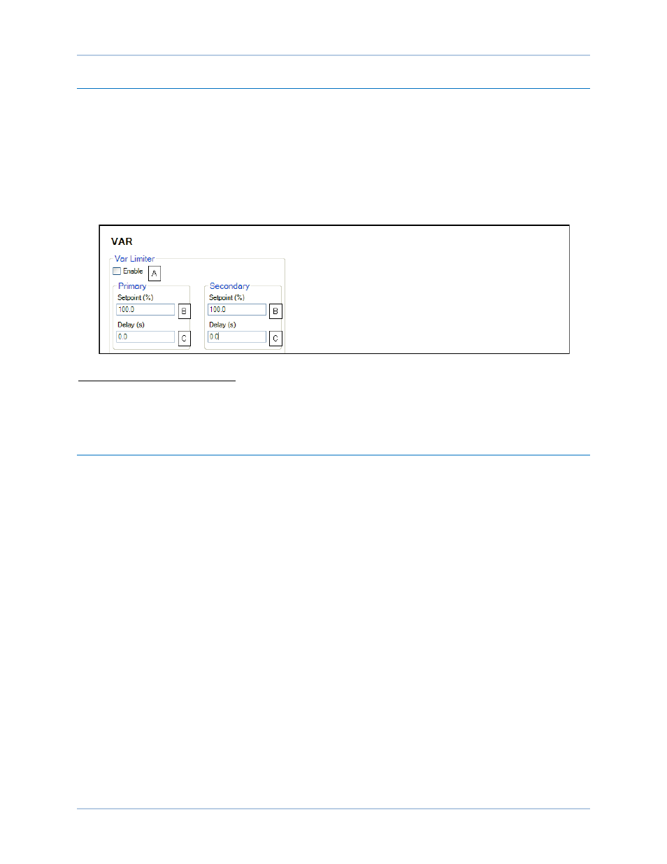
Var limiter settings are illustrated in Figure 52.
Figure 52. Var Limiter Settings
A
Var Limiter Enable: Select checkbox to enable var limiter.
B
Var Limiter Setpoint: Adjustable from 0 to 200% in 0.1% increments.
C
Var Limiter Delay: Adjustable from 0 to 300 s in 0.1 s increments.
Limiter Scaling
BESTCOMSPlus Navigation Path: Settings Explorer, Operating Settings, Limiters, Scaling
HMI Navigation Path: Settings, Operating Settings, Limiters, Scaling
Automatic adjustment (scaling) of the overexcitation limiter and stator current limiter is possible through
the DECS-250N auxiliary control input. Limiter scaling settings are illustrated in Figure 53. OEL and SCL
scaling may be independently enabled and disabled
A
. Automatic adjustment of the OEL and SCL is based
on six parameters: signal and scale for three points (levels).
With the scaling input set to Auxiliary Input, the signal value
B
for each point represents the auxiliary
control input. This input can be a 4 to 20 mAdc signal applied to terminals I+ and I– or a –10 to +10 Vdc
signal applied to terminals V+ and V–. (The input type is selected in BESTCOMSPlus). See the Auxiliary
Control chapter of this manual for details.
With the scaling input set to AEM RTD #, the signal value for each point represents an AEM RTD input in
degrees Fahrenheit. See the Analog Expansion Module chapter of the manual for details.
The scale value
C
for each point defines the limiter low level as a percent of rated field current for the OEL
and rated stator current for the SCL.