Analog outputs – Basler Electric DECS-250N User Manual
Page 347
9440500990 Rev D
331
DECS-250N
Analog Expansion Module
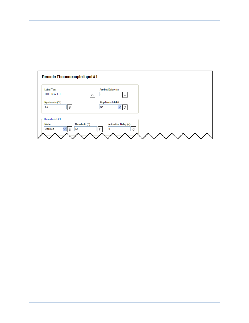
Each thermocouple input can be independently configured for over or under mode
E
to annunciate an
alarm when the thermocouple input signal falls beyond the threshold
F
. Alarms are configured on the Alarm
Configuration, Alarms screen in BESTCOMSPlus. A user-adjustable activation delay
G
setting delays
alarm annunciation after the threshold has been exceeded.
The remote thermocouple inputs are incorporated into a BESTlogicPlus programmable logic scheme by
selecting them from the I/O group in BESTlogicPlus. For more details, refer to the BESTlogicPlus chapter.
BESTCOMSPlus settings for remote thermocouple inputs are illustrated in Figure 179. Remote
Thermocouple Input #1 is shown.
Figure 179. Remote Thermocouple Input Settings
A
Label Text: An alphanumeric character string with a maximum of 64 characters.
B
Hysteresis: Adjustable from 0 to 100% in 0.1% increments.
C
Arming Delay: Adjustable from 0 to 300 s in 1 s increments.
D
Stop Mode Inhibit: Yes or No.
E
Mode: Disabled, Over, or Under.
F
Threshold: Adjustable from 32 to 2,507
°F in 1°F increments.
G
Activation Delay: Adjustable from 0 to 300 s in 1 s increments.
Analog Outputs
BESTCOMSPlus Navigation Path: Settings, Programmable Outputs, Remote Analog Outputs
HMI Navigation Path: Settings, Programmable Outputs, Remote Analog Outputs
The AEM-2020 provides four analog outputs.
Make a parameter selection
A
and select the output type
B
. An out-of-range alarm configured on the Alarm
Configuration, Alarms screen in BESTCOMSPlus, alerts the user of an open or damaged analog output
wire. An out-of-range activation delay
C
setting delays alarm annunciation.
Ranges must be set for the selected output type. Param Min
D
correlates to Min Output Current
E
or Min
Output Voltage
F
and Param Max
G
correlates to Max Output Current
H
or Max Output Voltage
I
.
The remote analog outputs are incorporated into a BESTlogicPlus programmable logic scheme by
selecting them from the I/O group in BESTlogicPlus. For more details, refer to the BESTlogicPlus chapter.
BESTCOMSPlus settings for remote analog outputs are illustrated in Figure 180. Remote Analog Output
#1 is shown.