Exciter diode monitor – Basler Electric DECS-250N User Manual
Page 66
50
9440500990 Rev D
Protection
DECS-250N
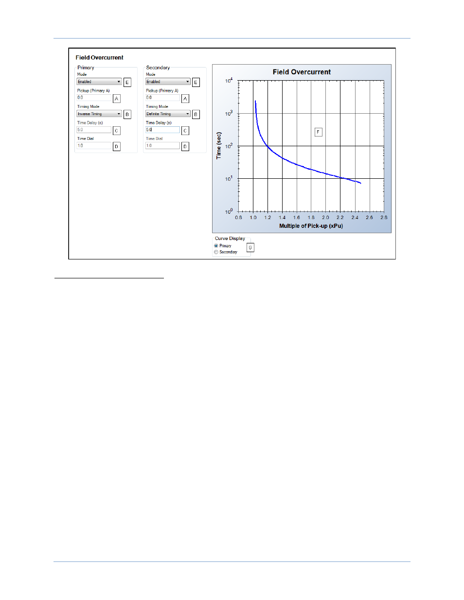
Figure 37. Field Overcurrent Protection Settings
A
Field Overcurrent Pickup (A): Adjustable from 0 to 22 Adc in 0.1 Adc increments.
B
Timing Mode: Select Definite Timing or Inverse Timing
C
Field Overcurrent Time Delay (s): Adjustable from 0 or 5 to 60 seconds in 0.1 second increments.
D
Field Overcurrent Time Dial: Adjustable from 0.1 to 20 in increments of 0.1.
E
Field Overcurrent Mode: Select Disabled or Enabled.
F
Inverse field overcurrent pickup curve.
G
Curve display selections.
Exciter Diode Monitor
The exciter diode monitor (EDM) monitors the condition of a brushless exciter’s power semiconductors by
monitoring the exciter field current. The EDM detects both open and shorted rotating diodes in the exciter
bridge. EDM settings are illustrated in Figure 38. When implementing the EDM, it is imperative that the
user know and specify the number of poles for the exciter armature and the generator rotor. For reliable
open diode detection, the exciter to generator pole ratio
A
should be 1.5 or higher and the level of field
current should be no less than 1.5 Adc. A pole ratio calculator, available in BESTCOMSPlus, can be used
to calculate the pole ratio from the number of exciter armature and generator rotor poles.