Bus voltage – Basler Electric DECS-250N User Manual
Page 31
9440500990 Rev D
15
DECS-250N
Voltage and Current Sensing
Note
If a machine is taken offline, then the secondary winding of that
machine’s cross-current compensation CT must be shorted.
Otherwise, the cross-current compensation scheme will not function.
Bus Voltage
Bus voltage monitoring enables bus failure detection, generator and bus voltage matching, and
synchronization of the generator with the utility/bus. These features are discussed in the Synchronizer
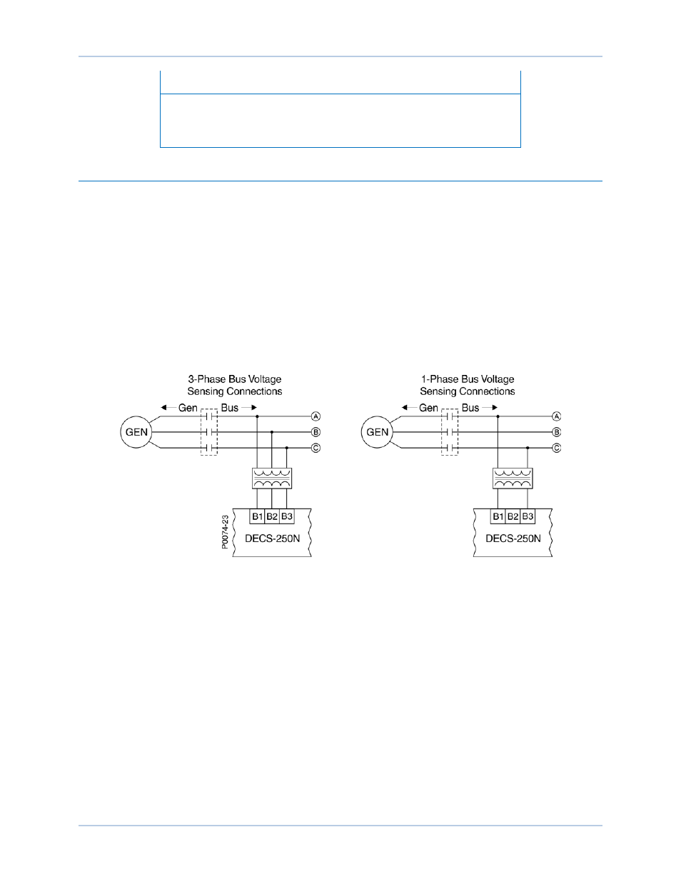
chapter of this manual. Three-phase bus sensing voltage is applied to DECS-250N terminals B1, B2, and
B3. This sensing voltage is typically applied through a user-supplied voltage transformer, but may be
applied directly. These terminals accept three-phase, three-wire connections at terminals B1 (A), B2 (B),
and B3 (C) or single-phase connections at B3 (C) and B1 (A).
The bus voltage sensing input accepts a maximum voltage of 600 Vac and has a burden of less than 1
VA.
The transformer primary and secondary winding voltages are entered in settings that the DECS-250N
uses to interpret the applied sensing voltage. Information about configuring the DECS-250N for the bus
sensing voltage is provided in the Configuration chapter of this manual.
Typical bus voltage sensing connections are illustrated in Figure 8.
Figure 8. Typical Bus Voltage Sensing Connections