2 vlan principles, 2 vlan principles -2 – H3C Technologies H3C S3100 Series Switches User Manual
Page 97
Operation Manual – VLAN
H3C S3100-52P Ethernet Switch
Chapter 1 VLAN Overview
1-2
A VLAN can span across multiple switches, or even routers. This enables hosts in a
VLAN to be dispersed in a looser way. That is, hosts in a VLAN can belong to different
physical network segment.
Compared with the traditional Ethernet, VLAN enjoys the following advantages.
z
Broadcasts are confined to VLANs. This decreases bandwidth utilization and
improves network performance.
z
Network security is improved. VLANs cannot communicate with each other
directly. That is, a host in a VLAN cannot access resources in another VLAN
directly, unless routers or Layer 3 switches are used.
z
Network configuration workload for the host is reduced. VLAN can be used to
group specific hosts. When the physical position of a host changes within the
range of the VLAN, you need not change its network configuration.
1.1.2 VLAN Principles
VLAN tags in the packets are necessary for the switch to identify packets of different
VLANs. The switch works at Layer 2 (Layer 3 switches are not discussed in this chapter)
and it can identify the data link layer encapsulation of the packet only, so you can add
the VLAN tag field into only the data link layer encapsulation if necessary.
In 1999, IEEE issues the IEEE 802.1Q protocol to standardize VLAN implementation,
defining the structure of VLAN-tagged packets.
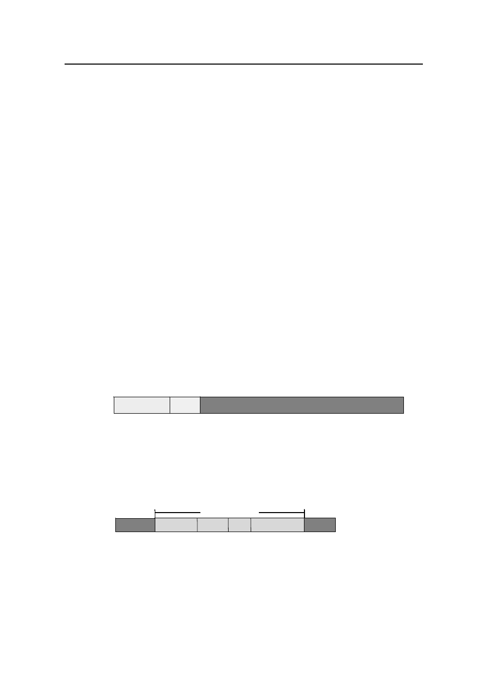
In traditional Ethernet data frames, the type field of the upper layer protocol is
encapsulated after the destination MAC address and source MAC address, as shown
in Figure 1-2
Type(2)
DA&SA(12)
DATA
Type
DA&SA(12)
DATA
DA&SA
DATA
Type(2)
DA&SA(12)
DATA
DA&SA(12)
DATA
Type
DA&SA(12)
DATA
DA&SA
DATA
Type(2)
DA&SA(12)
DATA
DA&SA(12)
DATA
Type
DA&SA(12)
DATA
DA&SA
DATA
Type(2)
DA&SA(12)
DATA
DA&SA(12)
DATA
Type
DA&SA(12)
DATA
DA&SA
DATA
Figure 1-2
Encapsulation format of traditional Ethernet frames
In Figure 1-2 DA refers to the destination MAC address, SA refers to the source MAC
address, and Type refers to the protocol type of the packet. IEEE 802.1Q protocol
defines that a 4-byte VLAN tag is encapsulated after the destination MAC address and
source MAC address to show the information about VLAN.
TPID Prioity CFI VLAN ID
VLAN Tag
DA&SA
TPID Prioity CFI VLAN ID
TPID Prioity CFI VLAN ID
TPID Prioity CFI VLAN ID
DA&SA
Type
TPID Prioity CFI VLAN ID
TPID Prioity CFI VLAN ID
TPID Prioity CFI VLAN ID
DA&SA
Type
TPID Prioity CFI VLAN ID
TPID Prioity CFI VLAN ID
TPID Prioity CFI VLAN ID
TPID Prioity CFI VLAN ID
DA&SA
Type
TPID Prioity CFI VLAN ID
VLAN Tag
TPID Prioity CFI VLAN ID
TPID Prioity CFI VLAN ID
VLAN Tag
DA&SA
Type
TPID Prioity CFI VLAN ID
TPID Prioity CFI VLAN ID
TPID Prioity CFI VLAN ID
TPID Prioity CFI VLAN ID
DA&SA
Type
TPID Prioity CFI VLAN ID
TPID Prioity CFI VLAN ID
TPID Prioity CFI VLAN ID
TPID Prioity CFI VLAN ID
DA&SA
Type
TPID Prioity CFI VLAN ID
TPID Prioity CFI VLAN ID
TPID Prioity CFI VLAN ID
TPID Priority CFI VLAN ID
DA&SA
Type
TPID Prioity CFI VLAN ID
VLAN Tag
TPID Prioity CFI VLAN ID
TPID Prioity CFI VLAN ID
VLAN Tag
DA&SA
Type
TPID Prioity CFI VLAN ID
TPID Prioity CFI VLAN ID
TPID Prioity CFI VLAN ID
TPID Prioity CFI VLAN ID
DA&SA
Type
TPID Prioity CFI VLAN ID
TPID Prioity CFI VLAN ID
TPID Prioity CFI VLAN ID
TPID Prioity CFI VLAN ID
DA&SA
Type
TPID Prioity CFI VLAN ID
TPID Prioity CFI VLAN ID
TPID Prioity CFI VLAN ID
TPID Prioity CFI VLAN ID
DA&SA
Type
TPID Prioity CFI VLAN ID
TPID Prioity CFI VLAN ID
VLAN Tag
TPID Prioity CFI VLAN ID
TPID Prioity CFI VLAN ID
VLAN Tag
DA&SA
Type
TPID Prioity CFI VLAN ID
TPID Prioity CFI VLAN ID
TPID Prioity CFI VLAN ID
TPID Prioity CFI VLAN ID
DA&SA
Type
TPID Prioity CFI VLAN ID
TPID Prioity CFI VLAN ID
TPID Prioity CFI VLAN ID
TPID Prioity CFI VLAN ID
DA&SA
Type
TPID Prioity CFI VLAN ID
TPID Prioity CFI VLAN ID
TPID Prioity CFI VLAN ID
TPID Priority CFI VLAN ID
DA&SA
Type
Type
g
Figure 1-3
Format of VLAN ta
As shown in Figure 1-3, a VLAN tag contains four fields, including TPID, priority, CFI,
and VLAN ID.
z
TPID is a 16-bit field, indicating that this data frame is VLAN-tagged. By default, it
is 0x8100 in H3C series Ethernet switches.