Ii. network diagram, Iii. configuration procedure – H3C Technologies H3C S3100 Series Switches User Manual
Page 221
Operation Manual – MSTP
H3C S3100-52P Ethernet Switch
Chapter 1 MSTP Configuration
1-46
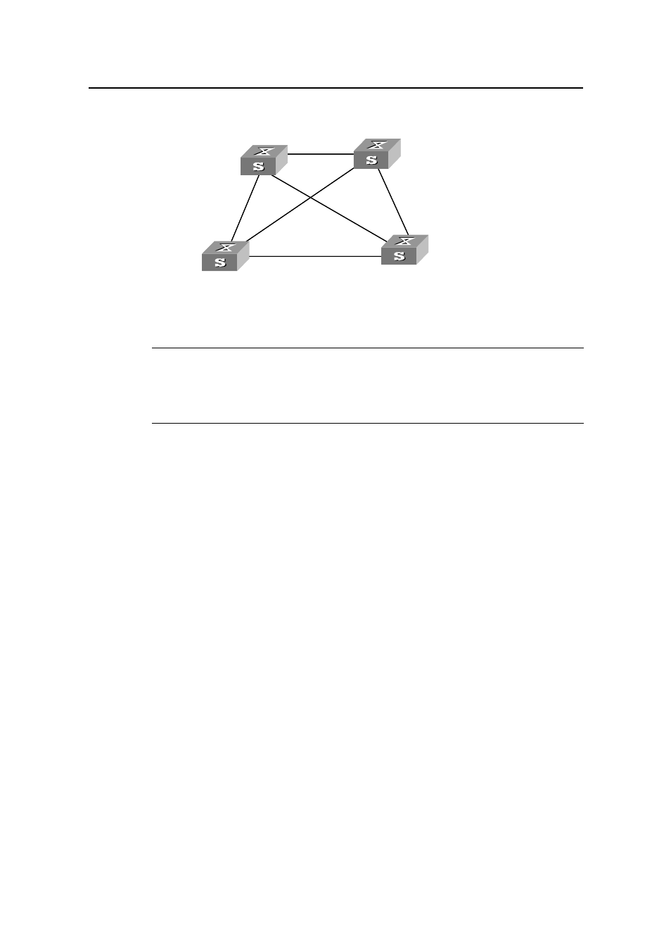
II. Network diagram
Switch A
Switch C
Switch B
Switch D
Permit :
VLAN 10, 20
Permit :
VLAN 10, 20
Permit :
VLAN 20, 30
Permit :
VLAN 20, 30
Permit :all VLAN
Permit :VLAN 20, 40
Switch A
Switch C
Switch B
Switch D
Permit :
VLAN 10, 20
Permit :
VLAN 10, 20
Permit :
VLAN 20, 30
Permit :
VLAN 20, 30
Permit :all VLAN
Permit :VLAN 20, 40
Figure 1-7
Network diagram for MSTP configuration
Note:
The word “permit” shown in Figure 1-7 means the corresponding link permits packets of
specific VLANs.
III. Configuration procedure
1) Configure Switch A
# Enter MST region view.
[H3C] stp region-configuration
# Configure the MST region.
[H3C-mst-region] region-name example
[H3C-mst-region] instance 1 vlan 10
[H3C-mst-region] instance 3 vlan 30
[H3C-mst-region] instance 4 vlan 40
[H3C-mst-region] revision-level 0
# Activate the settings of the MST region manually.
[H3C-mst-region] active region-configuration
# Specify Switch A as the root bridge of spanning tree instance 1.
[H3C] stp instance 1 root primary
2) Configure Switch B
# Enter MST region view.
[H3C] stp region-configuration