2 nm interface configuration example, I. network requirements, 2 nm interface configuration example -20 – H3C Technologies H3C S3100 Series Switches User Manual
Page 443
Operation Manual – Cluster
H3C S3100-52P Ethernet Switch
Chapter 1 Cluster
1-20
Note:
z
After completing the above configuration, you can execute the cluster switch-to
{ member-number | mac-address H-H-H } command on the management device to
switch to member device view to maintain and manage a member device. After that,
you can execute the cluster switch-to administrator command to return to
management device view.
z
In addition, you can execute the reboot member { member-number | mac-address
H-H-H
} [ eraseflash ] command on the management device to reboot a member
device. For detailed information about these operations, refer to the preceding
description in this chapter.
z
After the above configuration, you can receive logs and SNMP trap messages of all
cluster members on the NMS.
1.6.2 NM Interface Configuration Example
I. Network requirements
z
Configure VLAN-interface 2 as the NM interface of the switch;
z
Configure VLAN 3 as the management VLAN;
z
The IP address of the FTP server is 192.168.4.3;
z
The S3100-52P switch is the management switch;
z
The S3526E and S2403 switches are member switches.
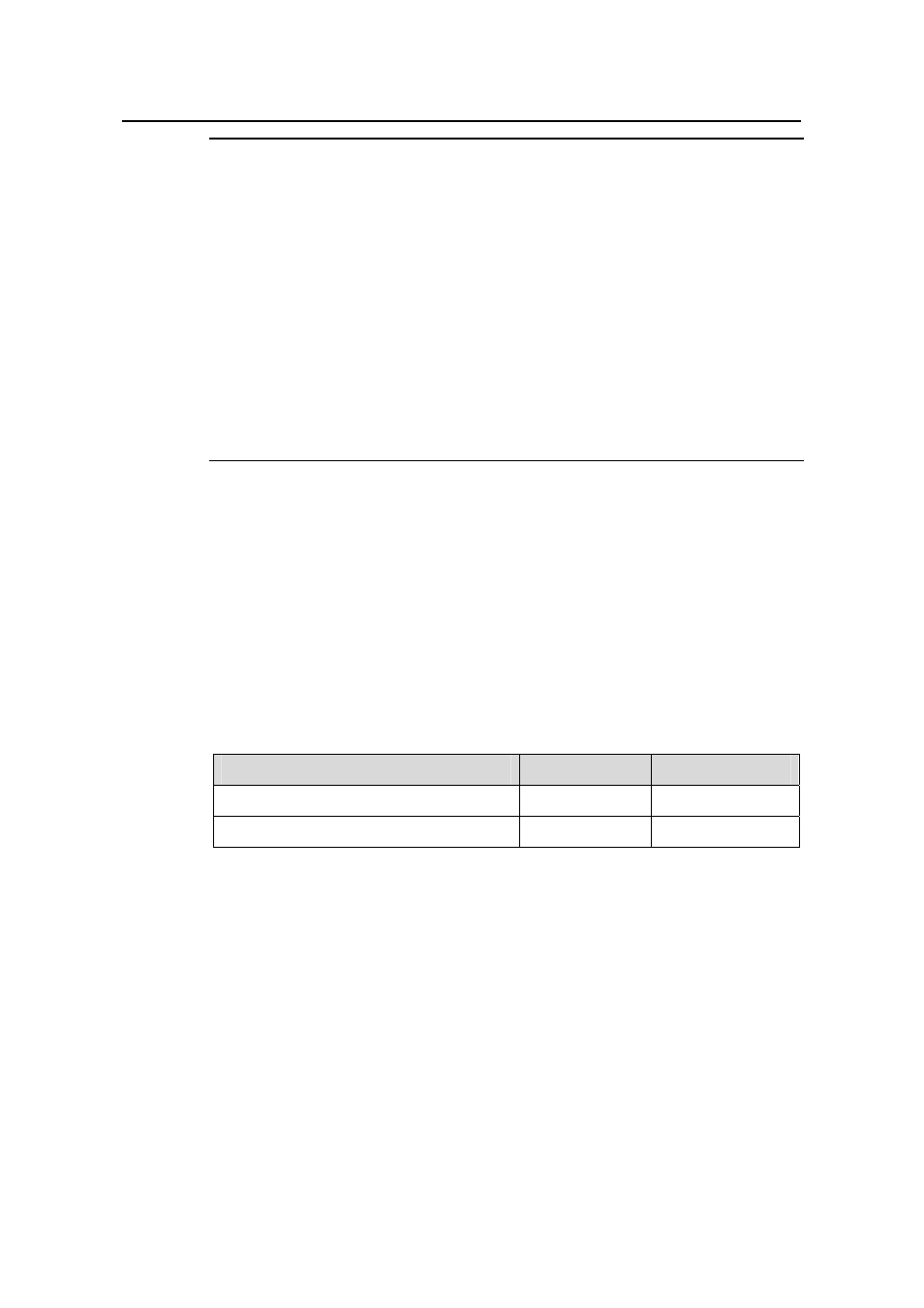
Table 1-19
Connection information of the management switch
VLAN
IP address
Connection port
VLAN 3 (connect to S3526E)
192.168.5.30/24 Ethernet 1/0/1
VLAN 2 (connect to FTP server) 192.168.4.22/24 Ethernet
1/0/2